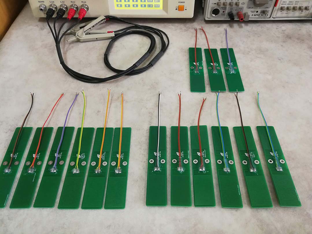
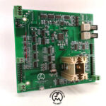
Working as a Teaching Assitant at the Faculty of Electronics, Bucharest I was also involved in research projects such as the current one, in which I modeled, simulated, and measured multiple variations of capacitive humidity sensors (Figure 1). Based on the findings of this work I also designed and manufactured a Humidity and Temperature Measurement Wireless Equipment (HTMWE) which I documented separately in this post. In the end, along with Mr. Razvan Craciunescu and Mr. Octavian Fratu, researchers from the Faculty of Electronics, Department of Telecommunications, I also wrote an article published in the prestigious Sensors MDPI Journal.
fringe field sensors
Hardware Design
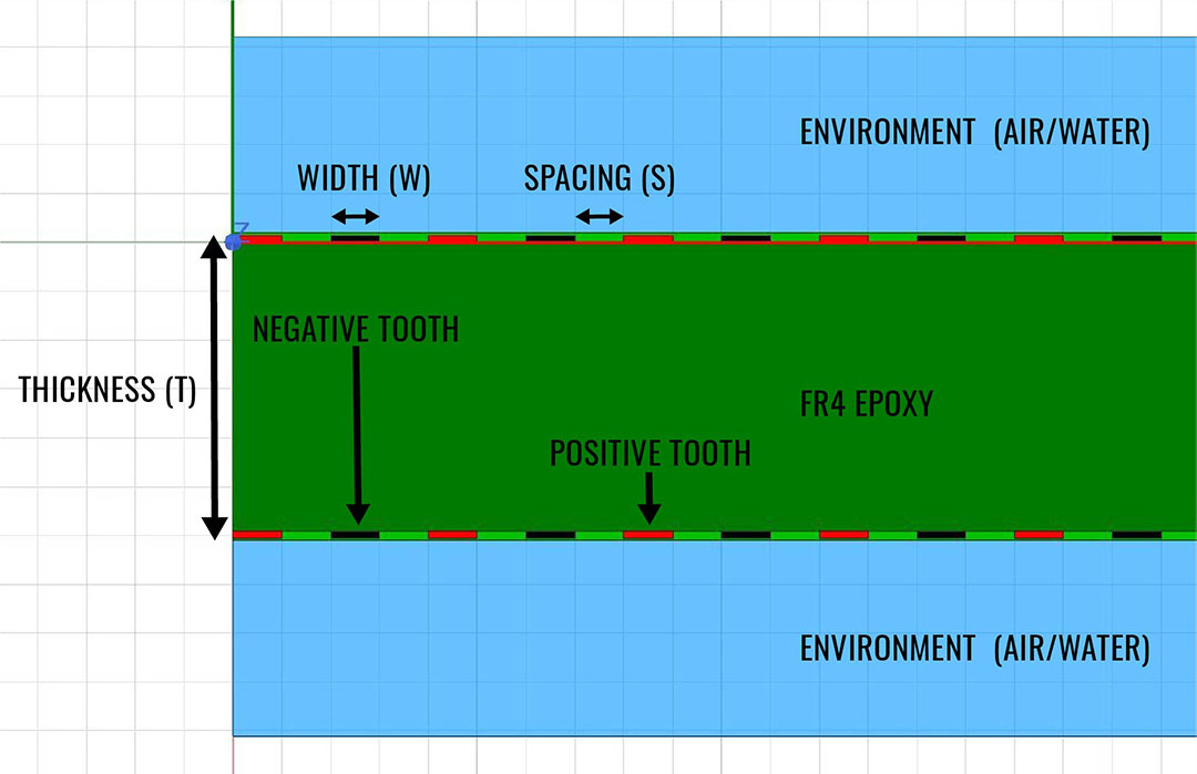
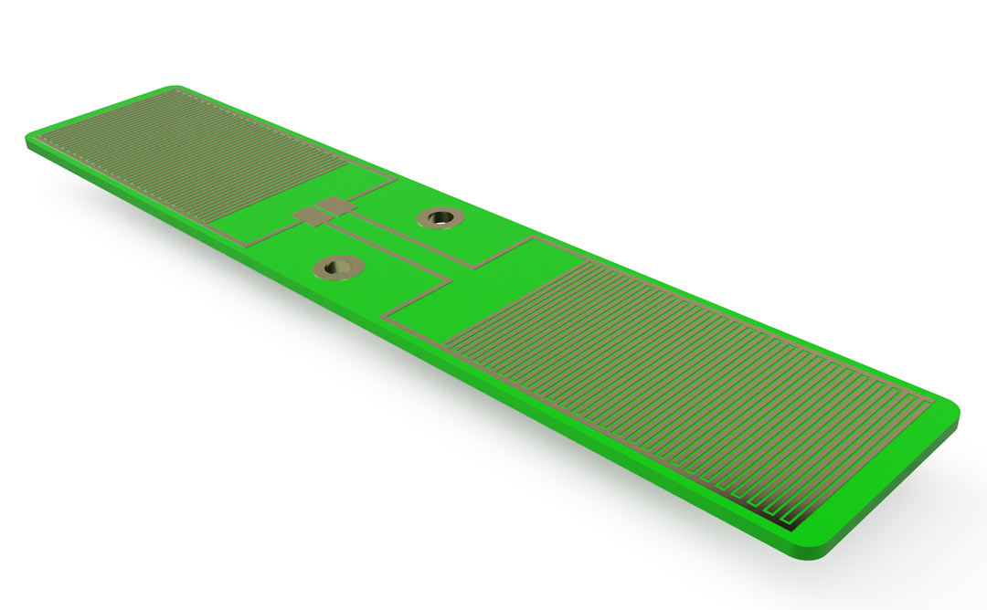
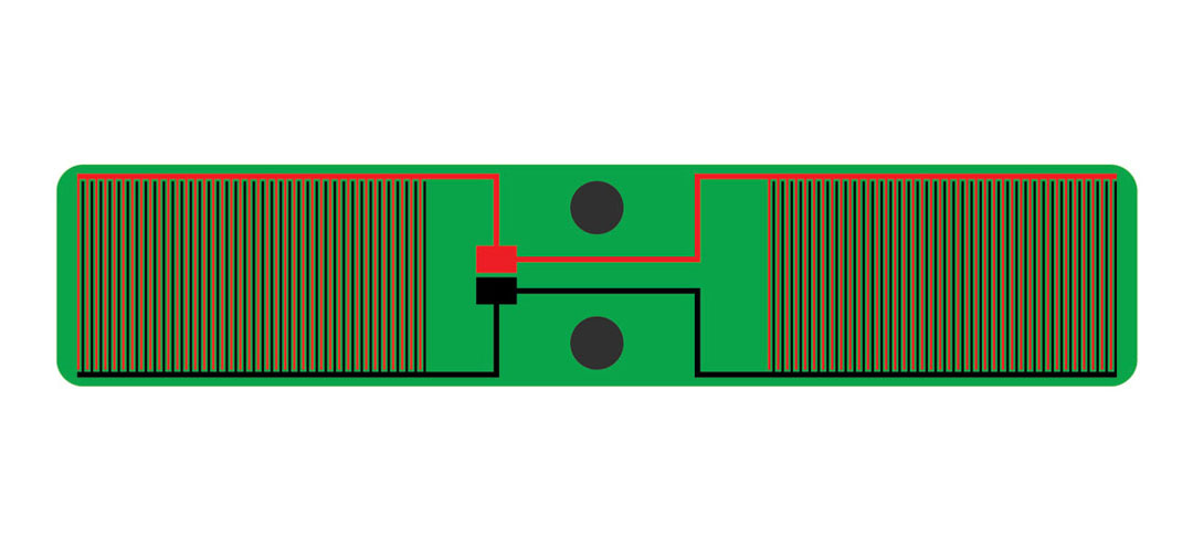
A capacitive humidity sensor is based on the fringing effect, the reason why they are also called fringe field sensors. As seen in Figures 2 and 3 this type of sensor, when implemented on a PCB structure, is composed of two electrodes each with many teeth interlaced one with another. The capacitance between these two electrodes depends on the dielectric constant (Dk) of the environment in which the sensor is immersed due to the fact that electric field lines pass through this environment. By adding as many as possible and as close as possible teeth for each electrode, you maximize the total capacitance of the sensor.


This investigation started with the scope of developing a Humidity and Temperature Measurement Wireless Equipment which as a state by its name has to measure both the temperature and the humidity of the soil. If for the temperature quantity there are many available sensors, not the same can be said about humidity. When I turned my attention towards manufacturing a custom PCB-made capacitive humidity sensor I could not find any guidelines in the current state of the art from publications and papers. In that context, I started investigating first by simulation and later by measurement (I simulated 30 different structures and manufactured 15 of them) how the Spacing – S and Width – W (see Figure 4) of the electrode teeth would affect the total capacitance and sensitivity of the sensor.
Simulation and Measurement
I started this investigation by simulating a variation of 30 structures for different values of Spacing – S and Width – W (in detail listed in the Sensors MDPI article available here). I was interested to obtain from the simulation a value for the capacitance of these structures and I was not interested in transmission line effects so I used ANSYS Q3D Extractor, a quasi-static field solver.
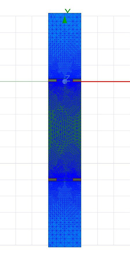
Because I had 30 designs to simulate and no more than the computational power of a regular laptop, I had to optimize as much as possible the simulation profile. For this, I reduced the capacitive structure to only a 2D section of the original geometry (simulated using the 2D version of Q3D Extractor) and I multiplied the results with the length of a tooth to obtain the total capacitance. Furthermore, I reduced it even more to only a single pair of teeth composed of 1/2 of the first, the gap, and 1/2 of the second (Figures 6 and 7), an operation performed only after I verified that additional coupling from other teeth can be safely omitted (Figure 5).
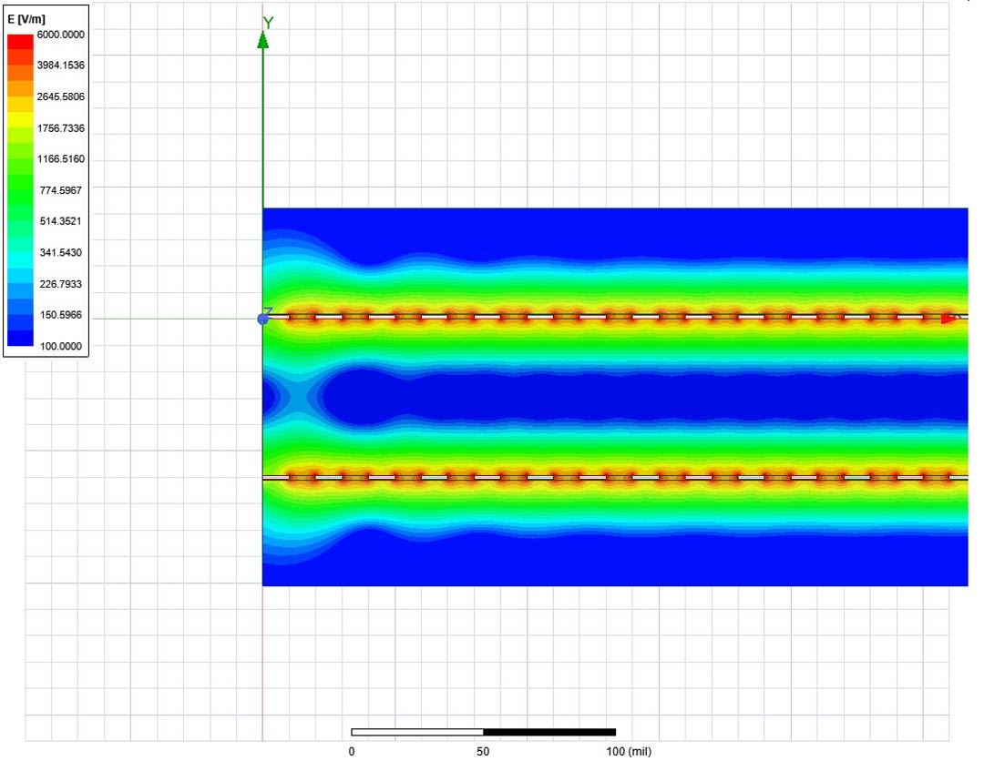
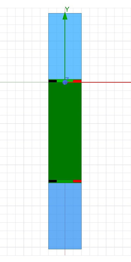
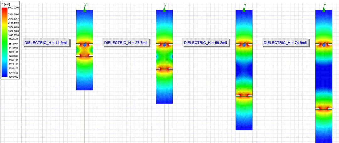
One other aspect I was interested to verify in this investigation was how the PCB dielectric substrate thickness affects the sensitivity of the sensor. Higher dielectric thickness leads to the electric field density inside the board lowering, as seen in Figure 8. This results in more electric field lines closing outside the board through the environment, which could lead to a higher sensitivity sensor. I validated through simulation this assumption but concluded that the gain in sensitivity was not high enough to justify the higher cost for thicker dielectric structures.
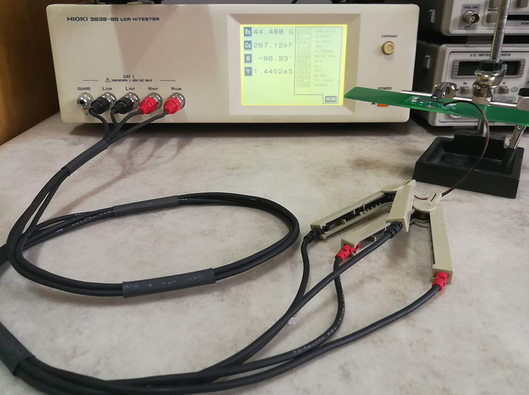
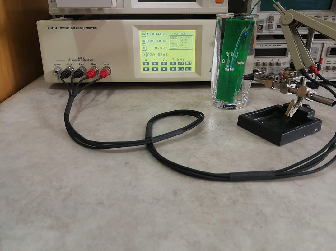
Another point of this investigation was LCR-measurements performed with a HIOKI-3532-50 LCR-meter for the 15 structures manufactured (Figures 9 and 10). Not presented in this post but in-depth discussed in the Sensors MDPI article available here, the measurement result matched the simulation results to a lower than 10% error.
Dissemination and Results
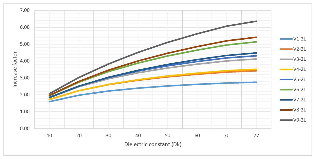
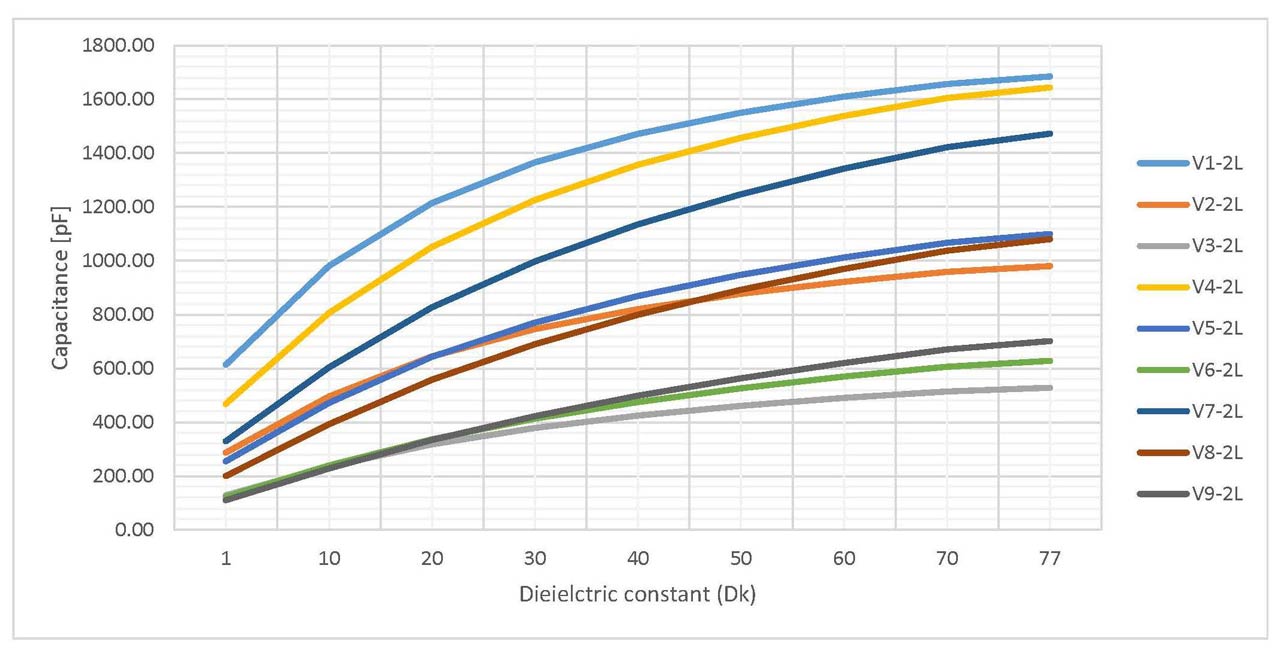
Finally presented in Figures 11 and 12 are the simulated results for 18 structures as capacitance and as increase factor. A very interesting result from this investigation was that a high capacitance sensor was not also a high sensitivity one. In fact, these two characteristics were part of a trade-off (the higher the first, the smaller the second). With the findings from this post about fringe field capacitive sensors I also developed a Humidity and Temperature Measurement Wireless Equipment (HTMWE) separately documented here.


