MicroEDMpulse was a project developed for EDMING SERV CONSULT, a Romanian company that provides automation solutions for, but not limited to, electro-erosion machines. MicroEDMpulse combines the electro-erosion process with ultrasound (US) vibrations. Even if this process is not new, the unique feature of this system is that it matches via an adaptive continuous process the electro-erosion discharge event with a certain time frame from the period of the US wave. In this way, the productivity of the machine is highly increased.
Right from the start, I must mention that my contribution to this project was only the redesign of existing electrical schematics and the full development of layout for the corresponding circuit boards, which was also my Master’s Thesis subject. Mr. Gheorghe Jitianu, Managing Director at EDMING SERV CONSULT and Lead Engineer for this project is fully credited for the microEDMpulse idea and has also two patents protecting his invention, RO 131031/2017 and RO 129537/2016.
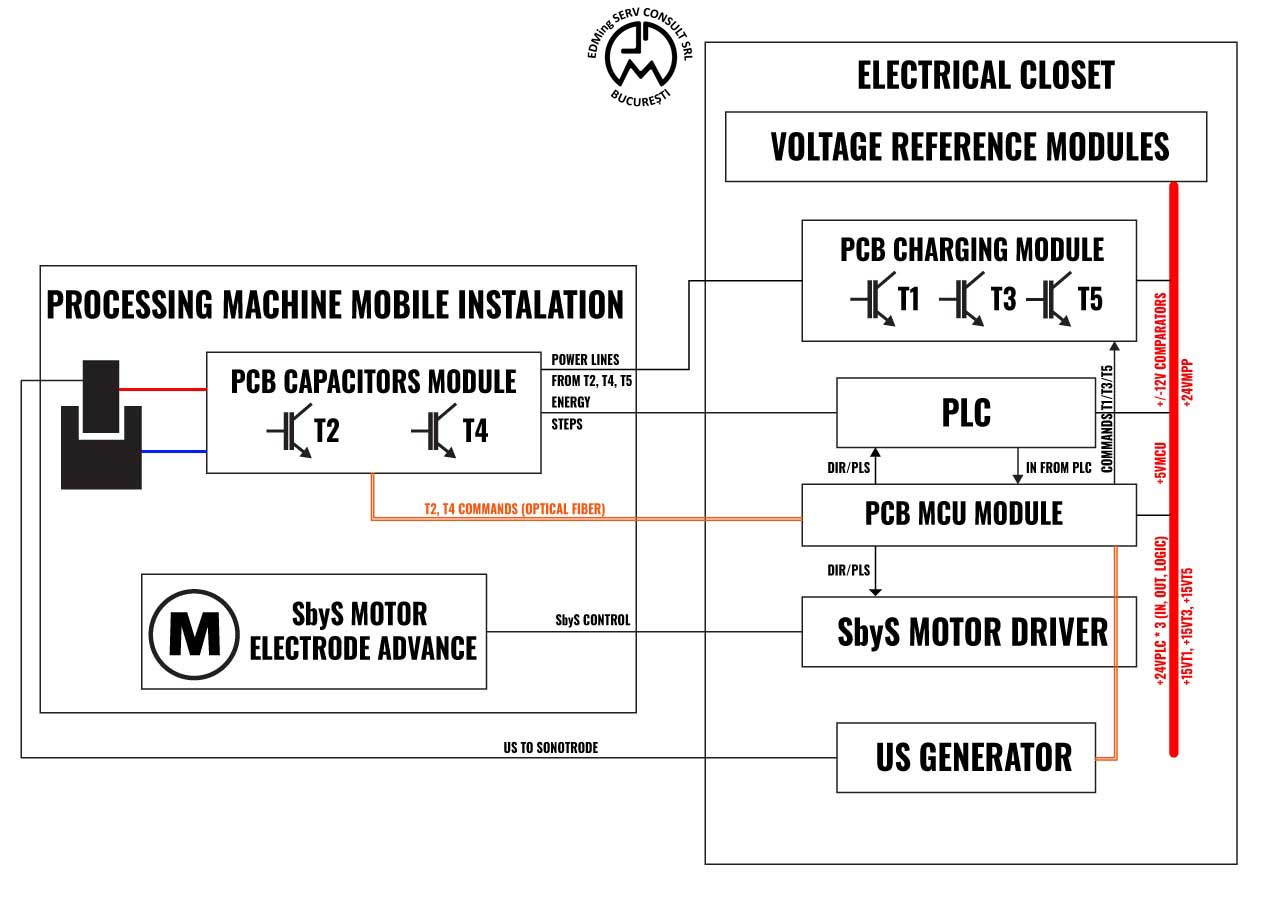
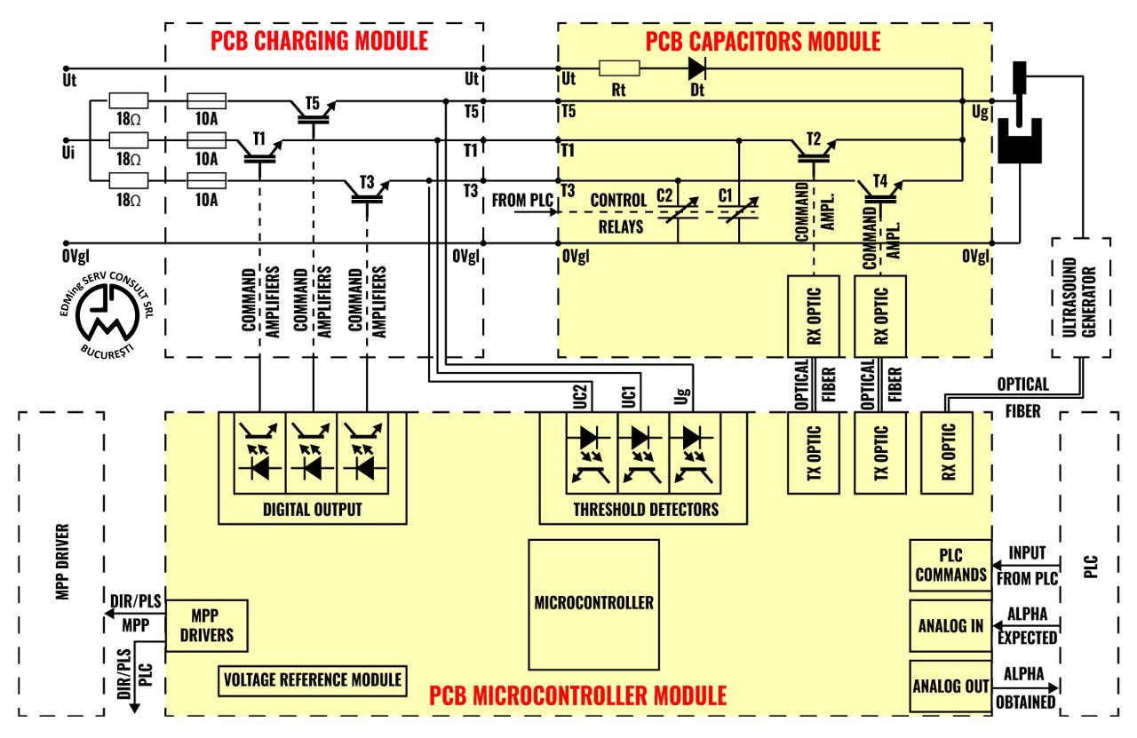
The whole microEDMpulse with the schematic from Figure 1 has multiple block components such as voltage reference modules, PLC ensuring the human-machine interface, SbyS motor and driver moving on the Z-axis the electrode closer or farther to the workpiece, US generator and lastly three PCB modules. I mention once again that the whole electrical system was designed by EDMING SERV CONSULT and my contribution is only related to the redesign of the three existing PCB modules, the Charging, MCU, and Capacitors ones. These three boards are furthermore electrically detailed in Figure 2. The Capacitors module is documented in this current post and the MCU one in a separate one, here.
The microEDMpulse system electrically erodes the workpiece by discharging the energy stored in several capacitor batteries located on the Capacitors module. The discharge of these capacitors takes place via the IGBT transistors T2 and T4 also located on the Capacitors module. The charging of these capacitors takes place via transistors T1 and T3 located on the Charging module, a separated PCB. The electrode-workpiece structure has a sonotrode attached, which makes it vibrate according to a US wave resulted from an external generator.
The main feature of the microEDMpulse system is that it can continuously match the discharge of the capacitors with a certain time frame from the period of the US wave. The value of this time frame is manually specified by the operator at the beginning of the electro-erosion process and varies with the material of the workpiece. Matching a purely random process as the electro-discharge of capacitors to a pre-defined time frame from a periodic wave is a complicated process done by the microcontroller from the MCU board. The embedded software from this microcontroller moves the electrode closer or apart to the workpiece by commanding the step by step motor. If the electrode-workpiece distance is smaller the electro-discharge will occur sooner in time or in the opposite case later.
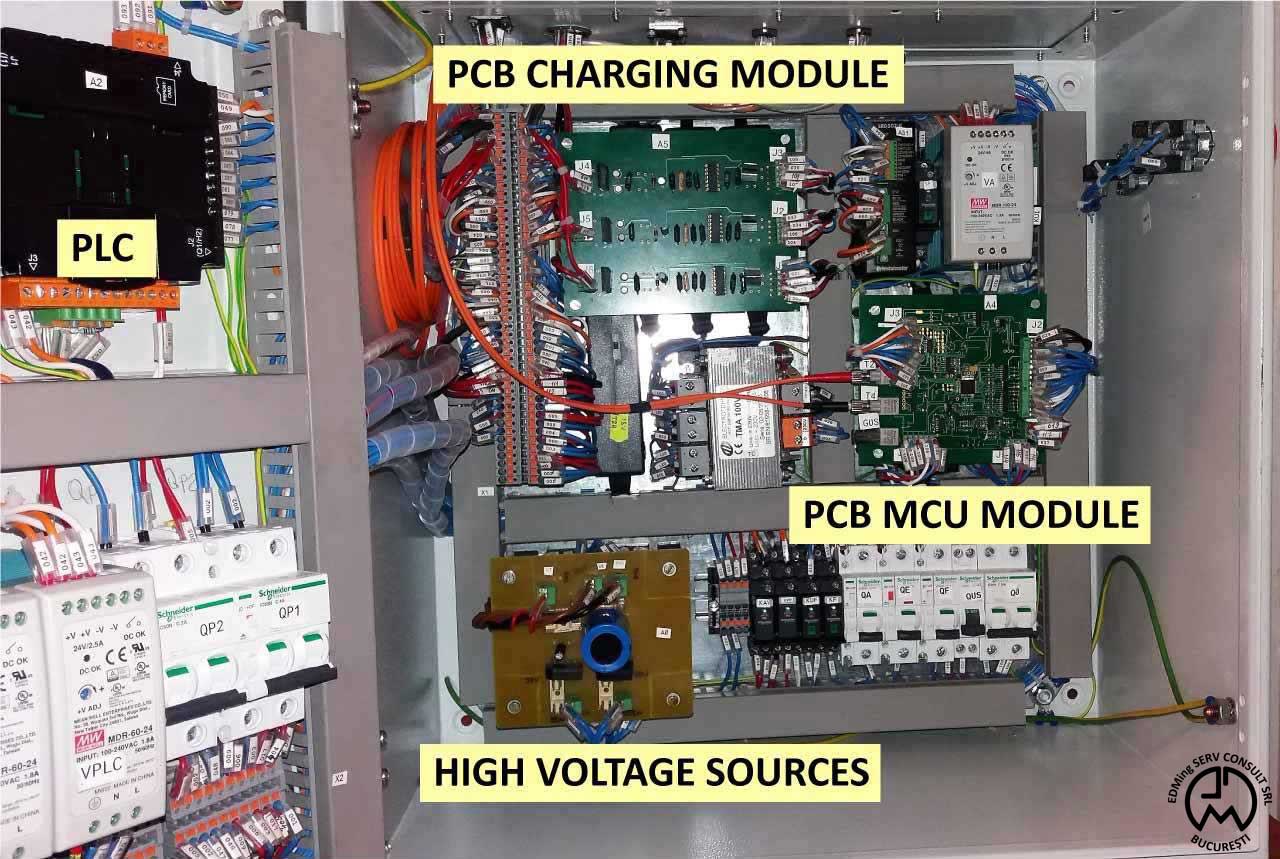
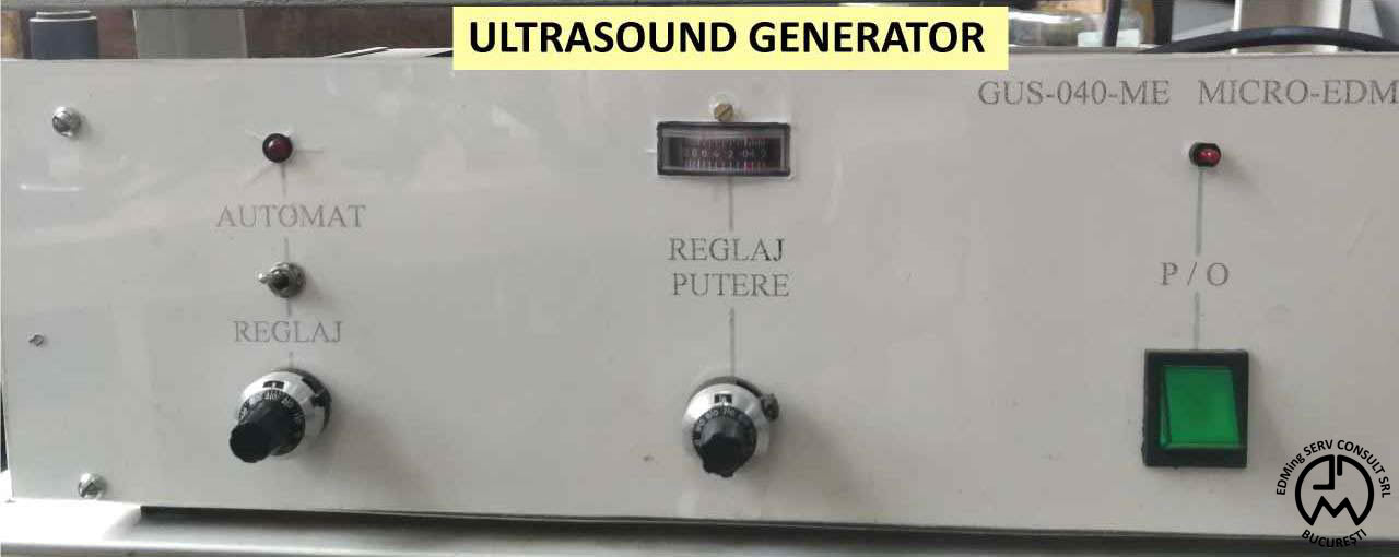
In Figure 3 is displayed the electrical closet with most of the electrical equipment residing here. You can observe the PCB Charging module and MCU module (old versions of them, designed before I got involved in this project). The US generator is an external one, displayed in Figure 4. As described in the schematic from Figure 2, it is both connected to the sonotrode which converts US waves into electrode vibrations, and also to the MCU module which requires the US signal as an input parameter.
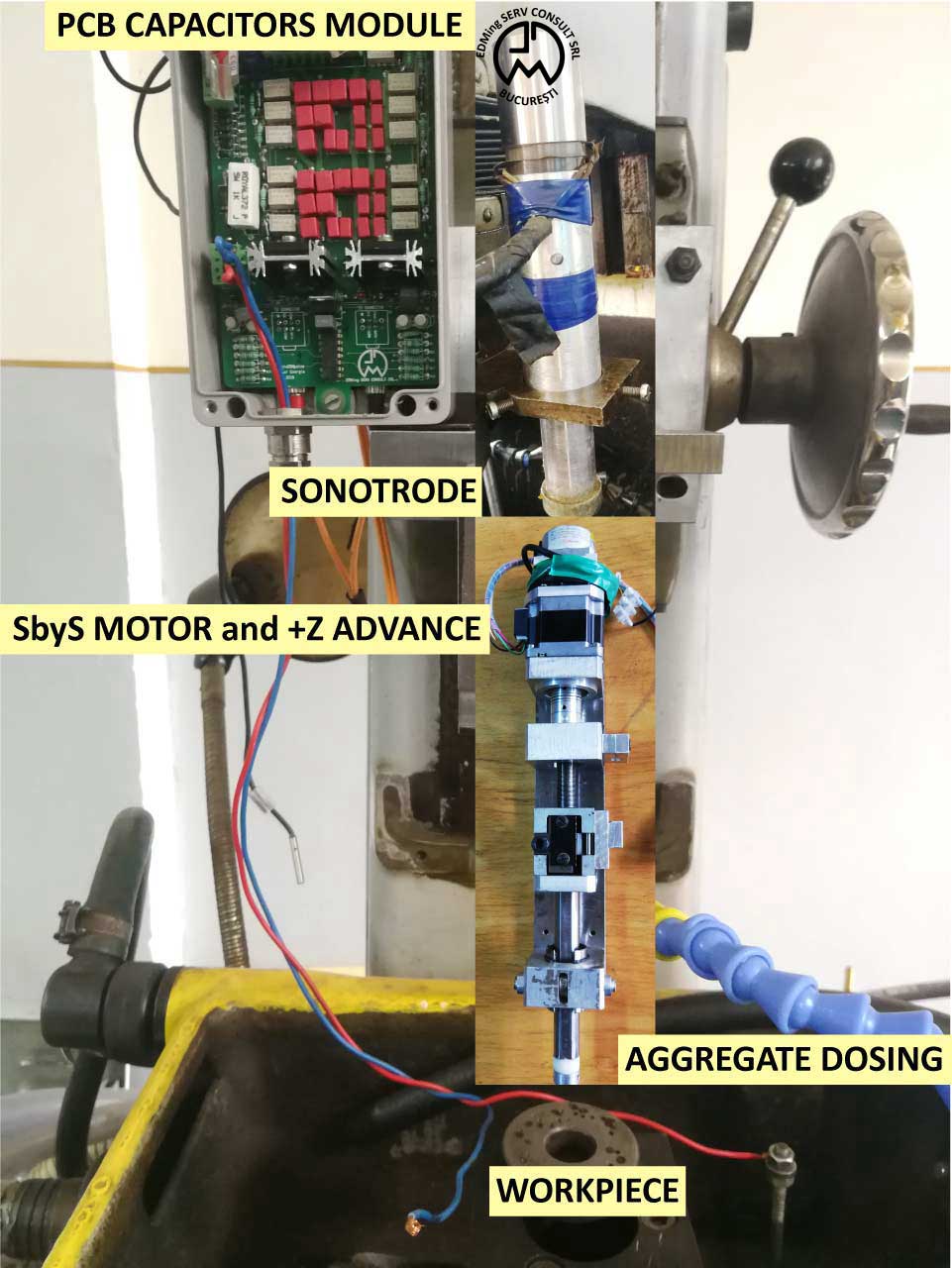
Unfortunately to the time when the images from this article were taken, parts of the microEDMpulse machine were disassembled, the reason why in Figure 5 only a collage of images is displayed. In this way, in Figure 5 you can observe the SbyS motor which advances the electrode on the +Z axis, the sonotrode vibrating the electrode according to the US wave, the Capacitors module, and finally the workpiece. The reason why the Capacitors module was placed as close as possible to the electrode-workpiece structure and not in the electric closet was to add as little as possible parasitic capacitance from the wires.
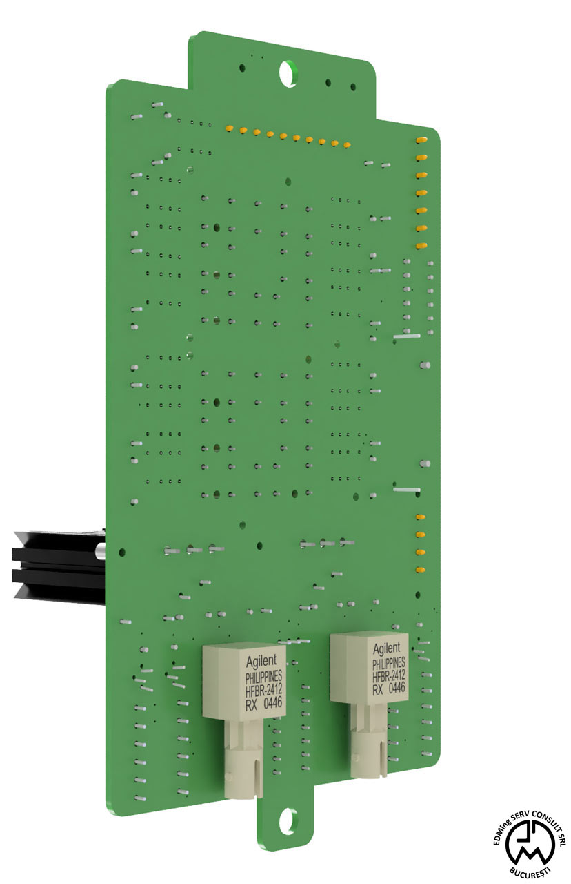
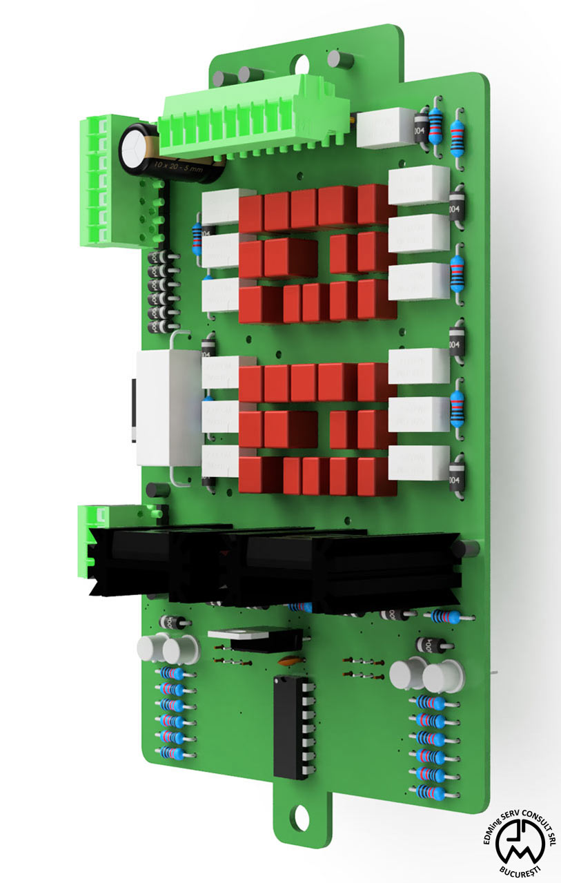
In Figures 6 and 7 you can observe a 3D rendered image for the Capacitors board generated from Autodesk Fusion 360. Notice how the board has the connectors precisely placed at specific coordinates on the margins as requested by the current existing wiring topology of the system. The board outline is designed to match the aluminum enclosure of the board with only two mounting holes on the two ends of the board. Optical fiber connectors are placed on the BOTTOM side.
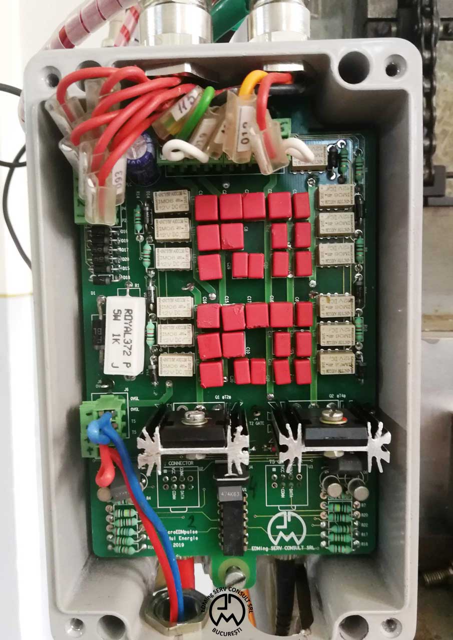
In Figure 8 is displayed the Capacitors board for the microEDMpulse machine. Even if the board had a reduced complexity as far as the layout was regarded, this project was still challenging for me because I had to first understand the whole application flow and complex electrical connections and then to design the circuit board. Following the design of the Capacitors module, I also worked on the MCU module, which is well documented as a separate post here.