The Humidity and Temperature Measurement Wireless Equipment (HTMWE) was part of a larger investigation that I performed along with Mr. Razvan Craciunescu and Mr. Octavian Fratu, researchers from the Faculty of Electronics, Department of Telecommunications. This investigation resulted in an in-depth article published in the prestigious Sensors MDPI Journal available here. The findings of this article are divided into two separate posts, the first on fringe field sensors and the current one about HTMWE.
HTMWE
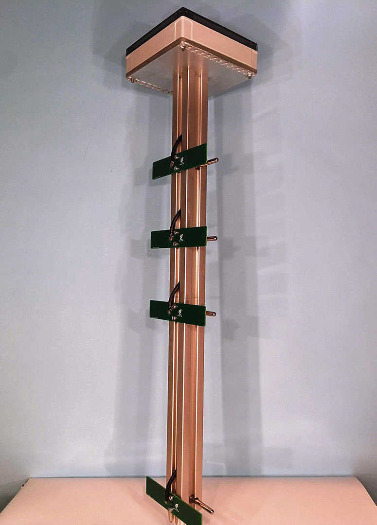
The HTMWE was a device designed to measure the temperature and humidity of the soil and sent it via LoRa to a central base station from which it was further uploaded into a cloud server. The two quantities of interest were measured at the specific depths of 5, 15, 25, and 50 cm as a resulted of discussions we had with experts from the National Institute of Agricultural Research-Development Fundulea, Romania. The system was powered by a Li-Ion battery charged through a solar cell. As seen in Figure 1, I used the custom-made capacitive humidity sensors that resulted from the findings in this previous project and also manufactured a structure where all the electronics were enclosed in a box above the ground.
Hardware Design
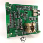
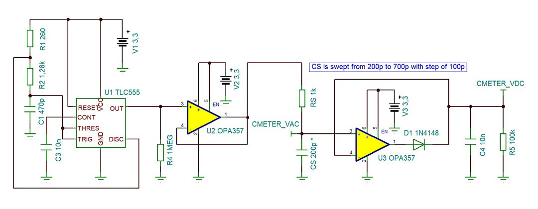
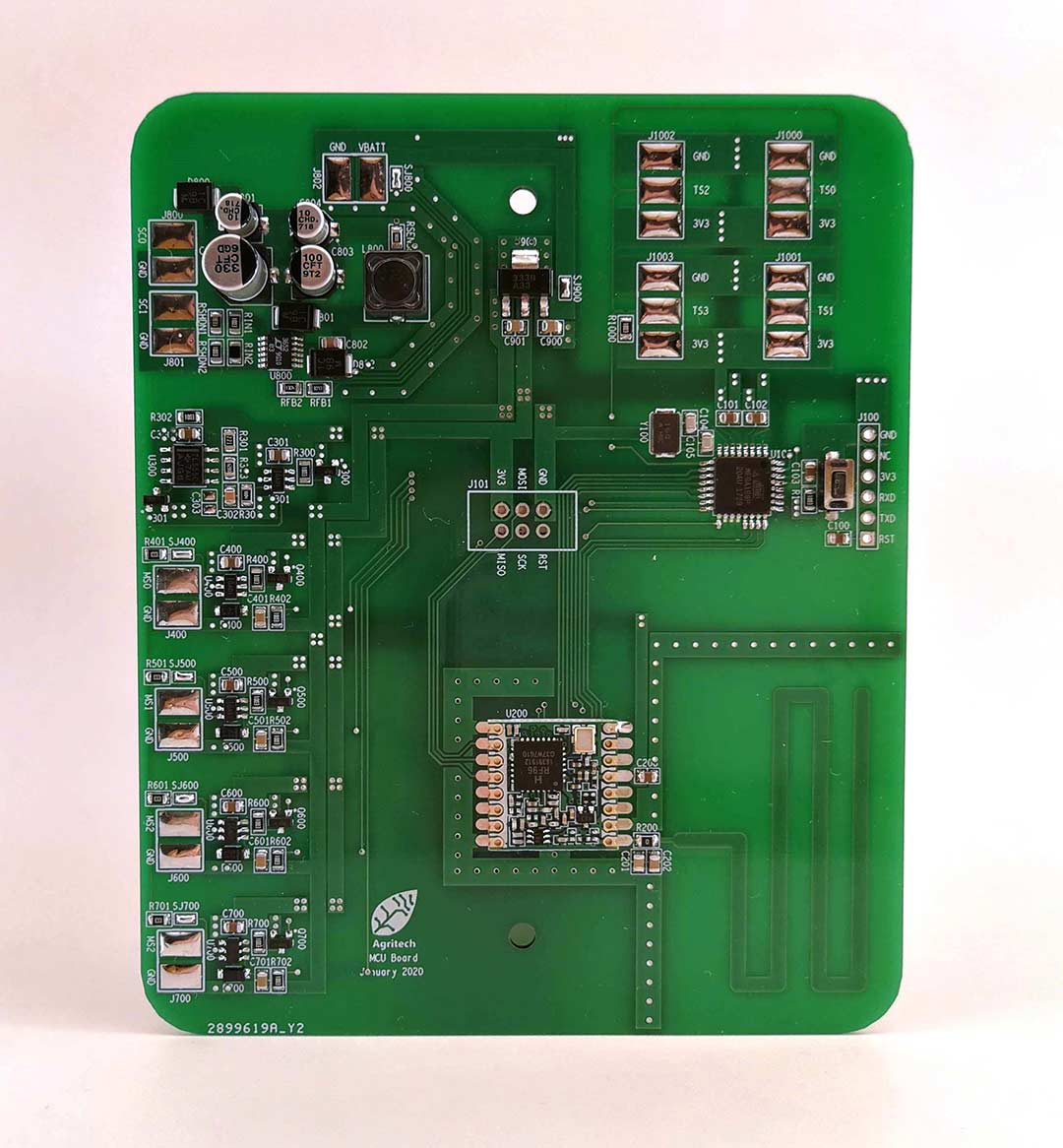
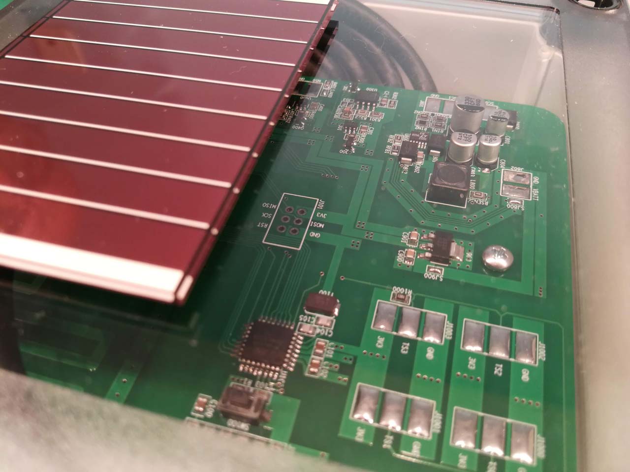
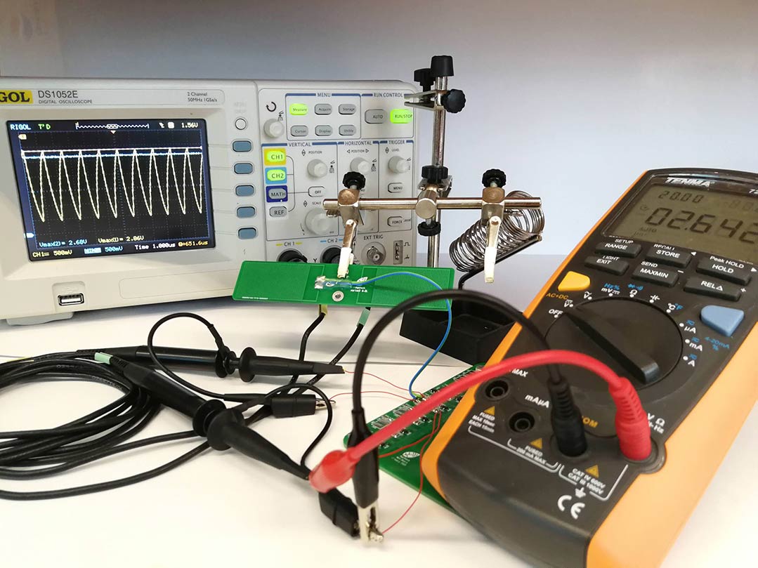
Presented in Figure 3 is the circuit board for the HTMWE equipment. Notice in the lower-right part the LoRa RFM95 Module with an integrated onboard antenna, on the left side four capacitance measurement circuits, and a battery charger from solar power based on LT3652 on the top-left side. For measuring the capacitance of the humidity sensors I designed a circuit converting its value into an analog voltage as described in detail in the article from Sensors MDPI (a square wave generator with TLC555 and peak voltage at the capacitor’s terminals is directly related to its capacitance). The electrical schematic of this capacitance measurement circuit is displayed in Figure 2.
Product Design
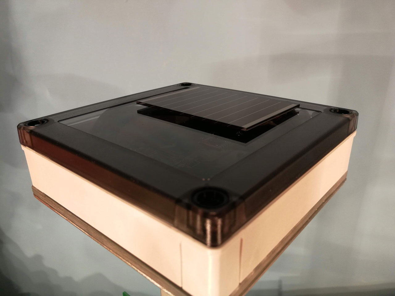
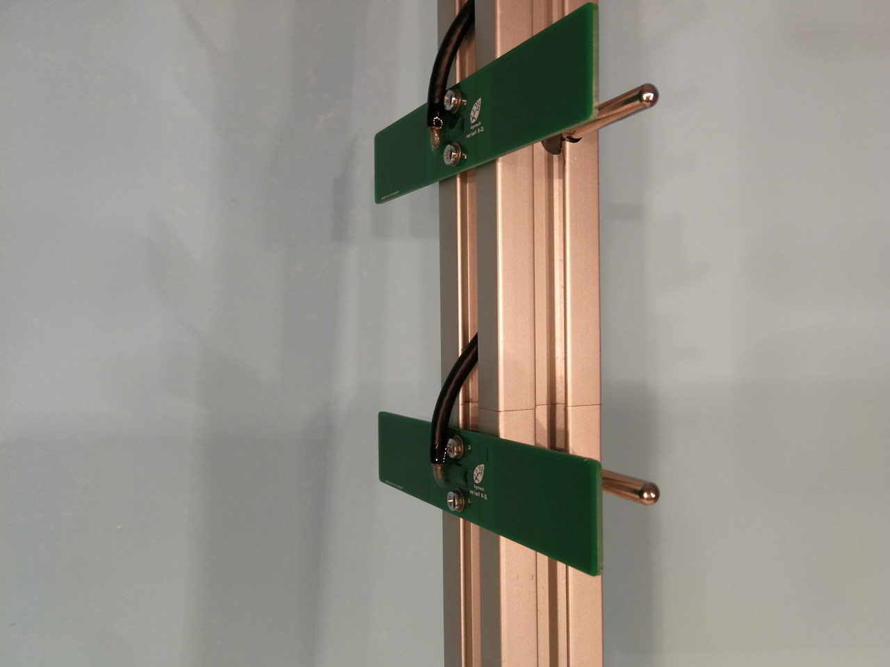
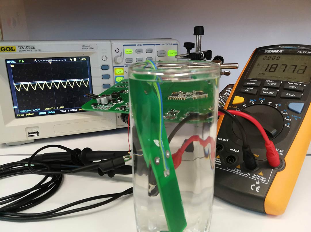
From Figures 4 and 5 you can observe the electronics board of HTMWE enclosed in the IP67 sealed box with the solar cell placed above. Below the electronics board inside the box is also placed a Li-Ion battery element. As seen in Figure 6, the capacitive sensors are connected with a controlled impedance coaxial cable (controlled impedance also leads to controlled capacitance). The exposed pads where the coaxial cable is soldered to the PCB capacitive structures were sealed with epoxy resin.
Simulation and Measurement
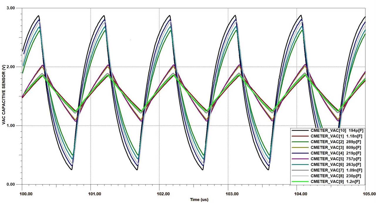
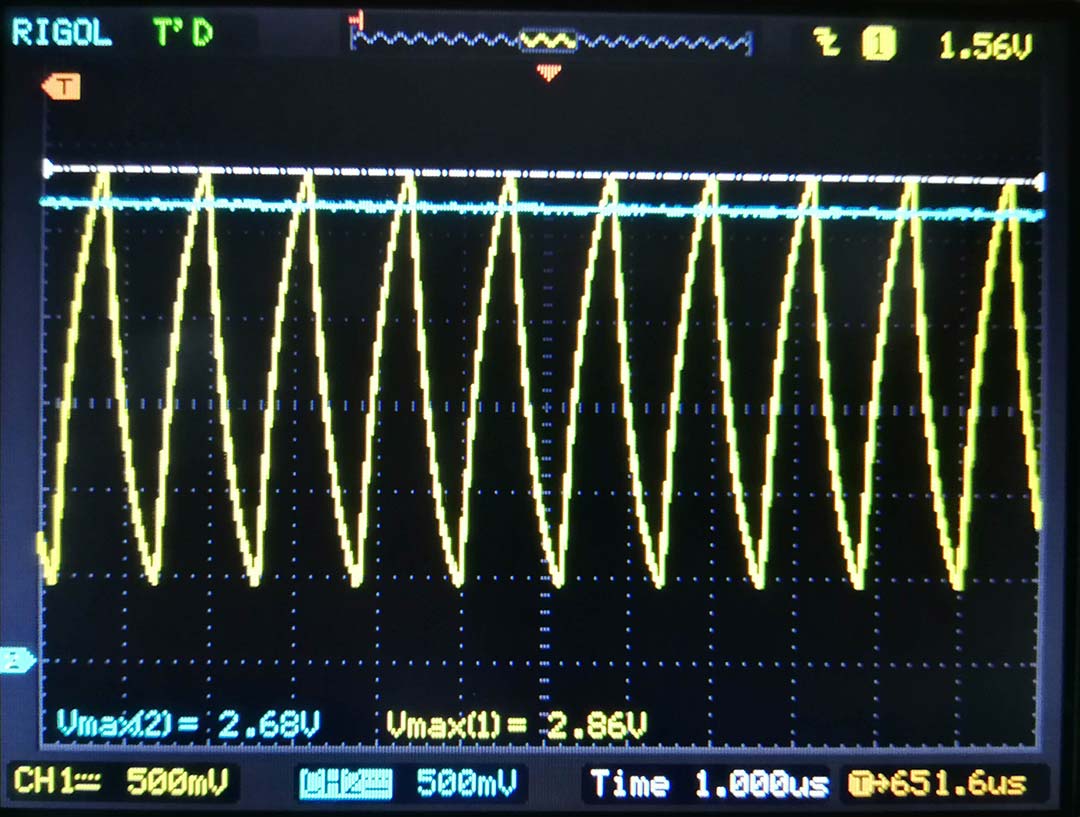
I simulated the capacitance measurement circuit from Figure 2 in Tina-TI and the waves from Figure 7 that represent the voltage at the capacitor’s terminals were obtained. As the capacitance is smaller, the peak value of the voltage is higher. As presented in Figures 8 to 11 I also investigated using a Rigol DS1052E oscilloscope the capacitance measurement with various sensors from the previous fringe field sensors investigation and the measurements matched the Tina-TI simulation to an error lower than 10%.

I can now say that the HTMWE project along with the previous fringe field sensors investigation were two research and development projects from which I learned a lot and that helped me gain more insight into the field of measurement, simulation, and modeling. As far as the development is regarded, I manufactured a completely functional HTMWE equipment and wrote the embedded C code to retrieve the data from sensors and transmit it to a base station device.