In 2016’s winter I came across some 8 segment bar graph arrays and I decided to use them in a LED VU Meter device since I was also looking at that time for a project involving audio. This is how Soundwaze was born, which also includes two potentiometers for fine-tuning the sound threshold and sensitivity, a Li-Po battery, and an on-board charging circuit. A public git repository is also available here for Soundwaze.
soundwaze
Hardware Design
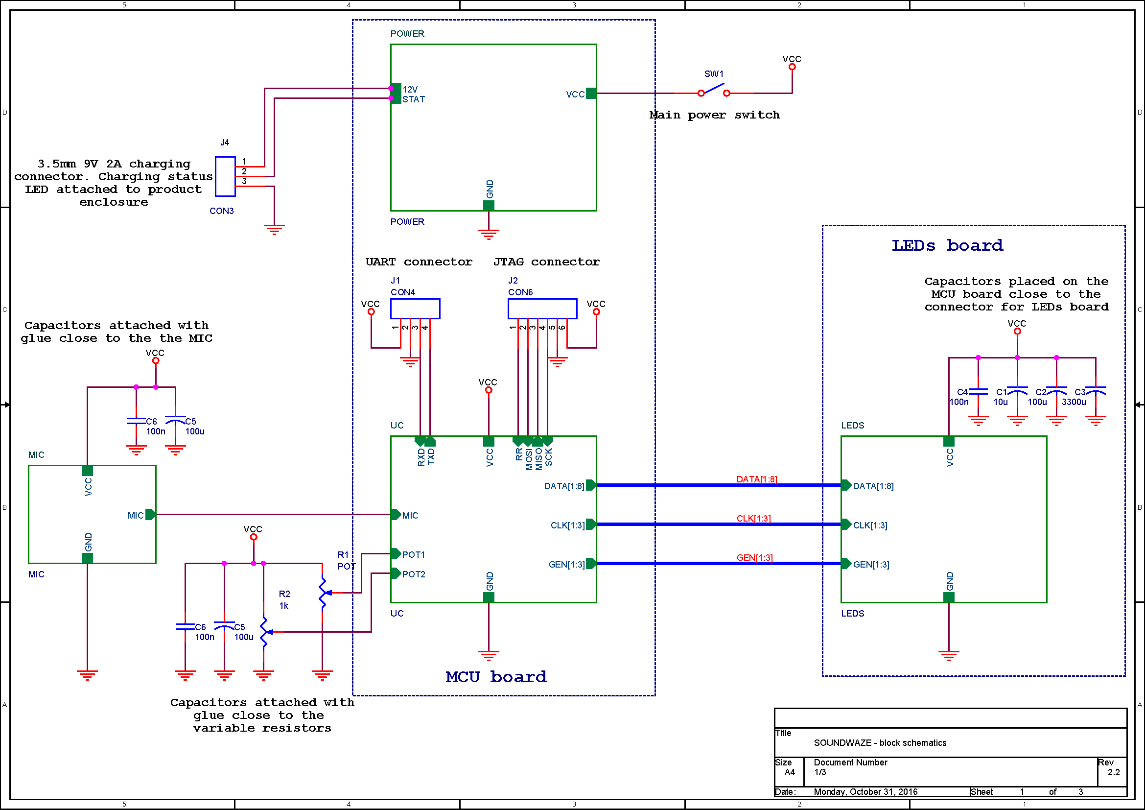
Displayed in Figure 1 is the block schematics for the developed system. The microphone was a Sparkfun breakout board. The POWER and UC blocks were placed on the same custom-made board, MCU board. The LEDs, latches, MOS transistors, and resistors were placed on a separated custom-made board, LEDs board.
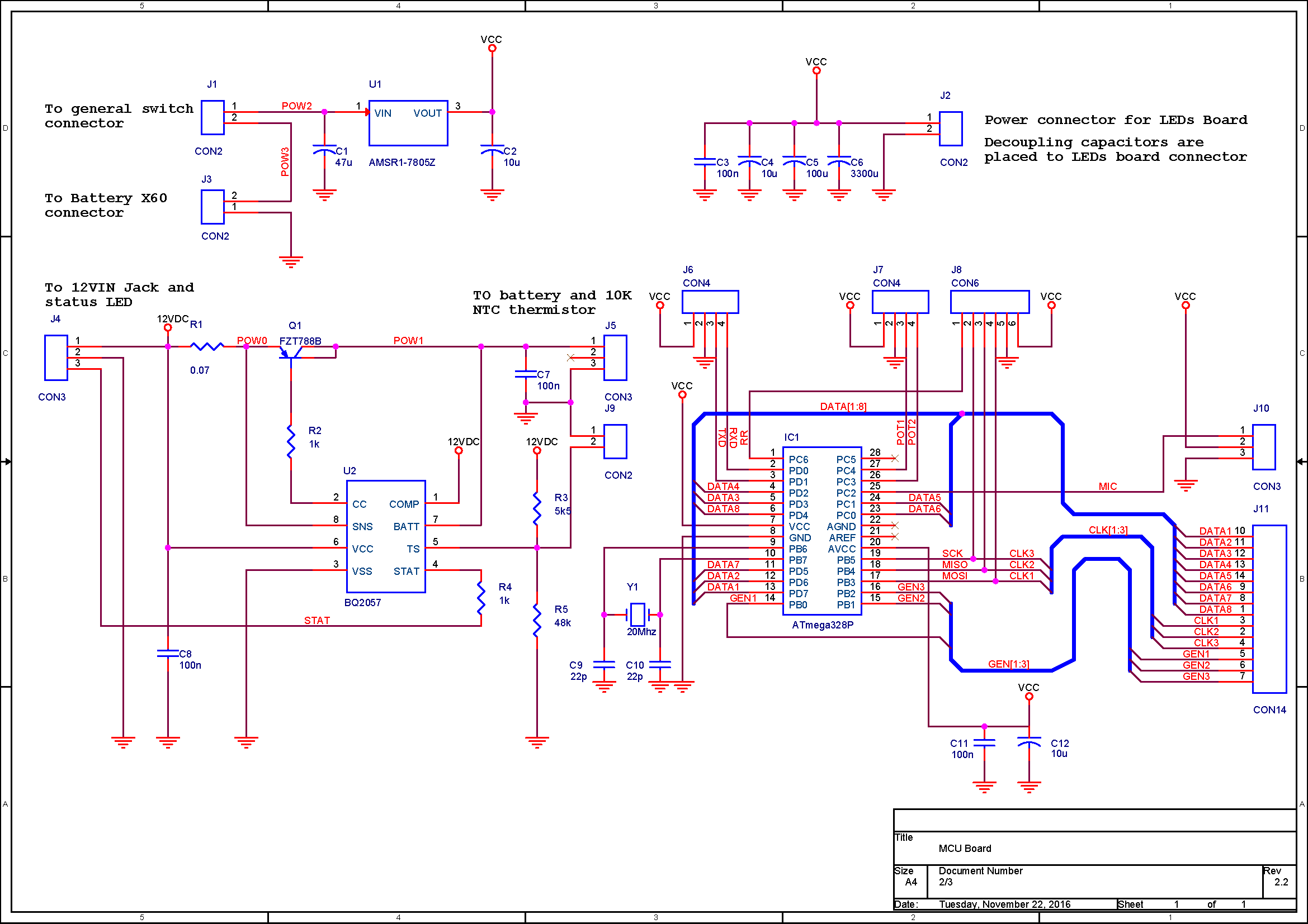
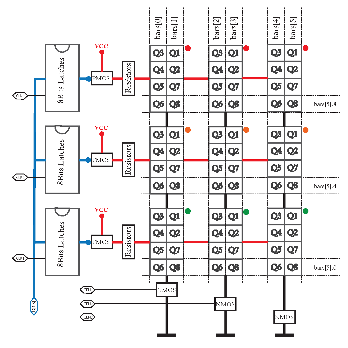
Displayed in Figure 2 is the electrical schematic for the MCU board, which contains the microcontroller and its crystal, the battery charging circuit, decoupling capacitors, voltage regulator, and connectors. In Figure 3 you can see a general schematic for the LEDs board, where all the LED segments from one row have the anode common and all the ones from one column have the cathode common. Anodes are controlled via PMOS transistors and the cathodes via NMOS transistors.
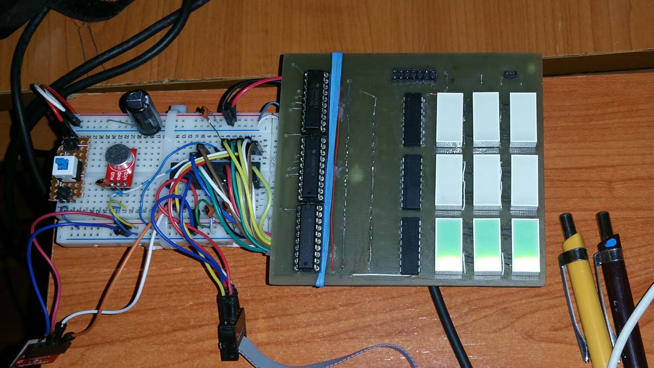
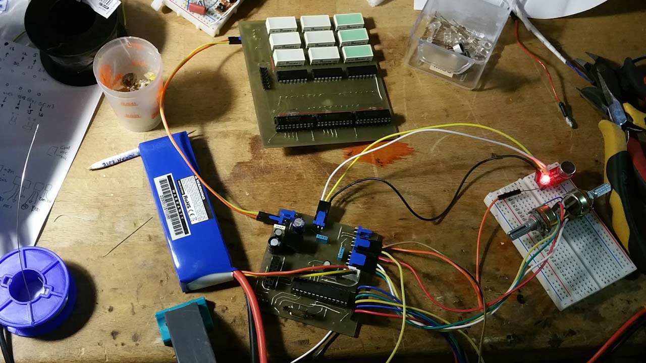
After I quickly manufactured the LEDs board and also soldered all the components I started the initial tests and debugging using a breadboard implementation for the rest of the electronics involved in the system. You can observe in Figure 4 this type of implementation.
Software Design
When it comes to embedded microcode, I opted for a bare-metal C code written using AVR Studio for the Atmega 328P microcontroller of this project. Of course, I could have quickly run towards an Arduino approach but I wanted to be able to control every aspect of the software loop running inside the MCU and to use and catch some interrupt events in a clear manner. This was not the first time I had written bare-metal C code for an Atmel MCU, having already the experience from Sequenster.
PCB Fabrication and Assembly
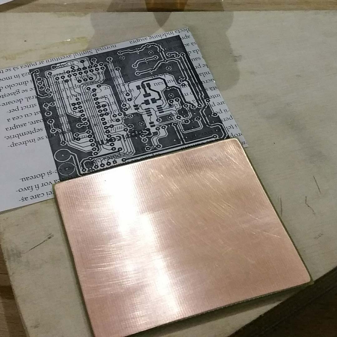
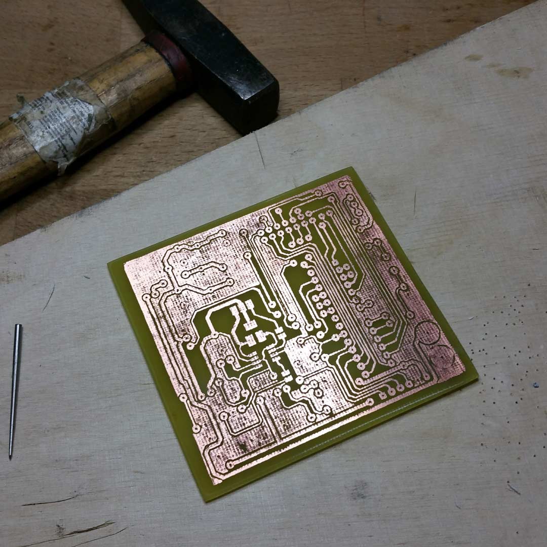
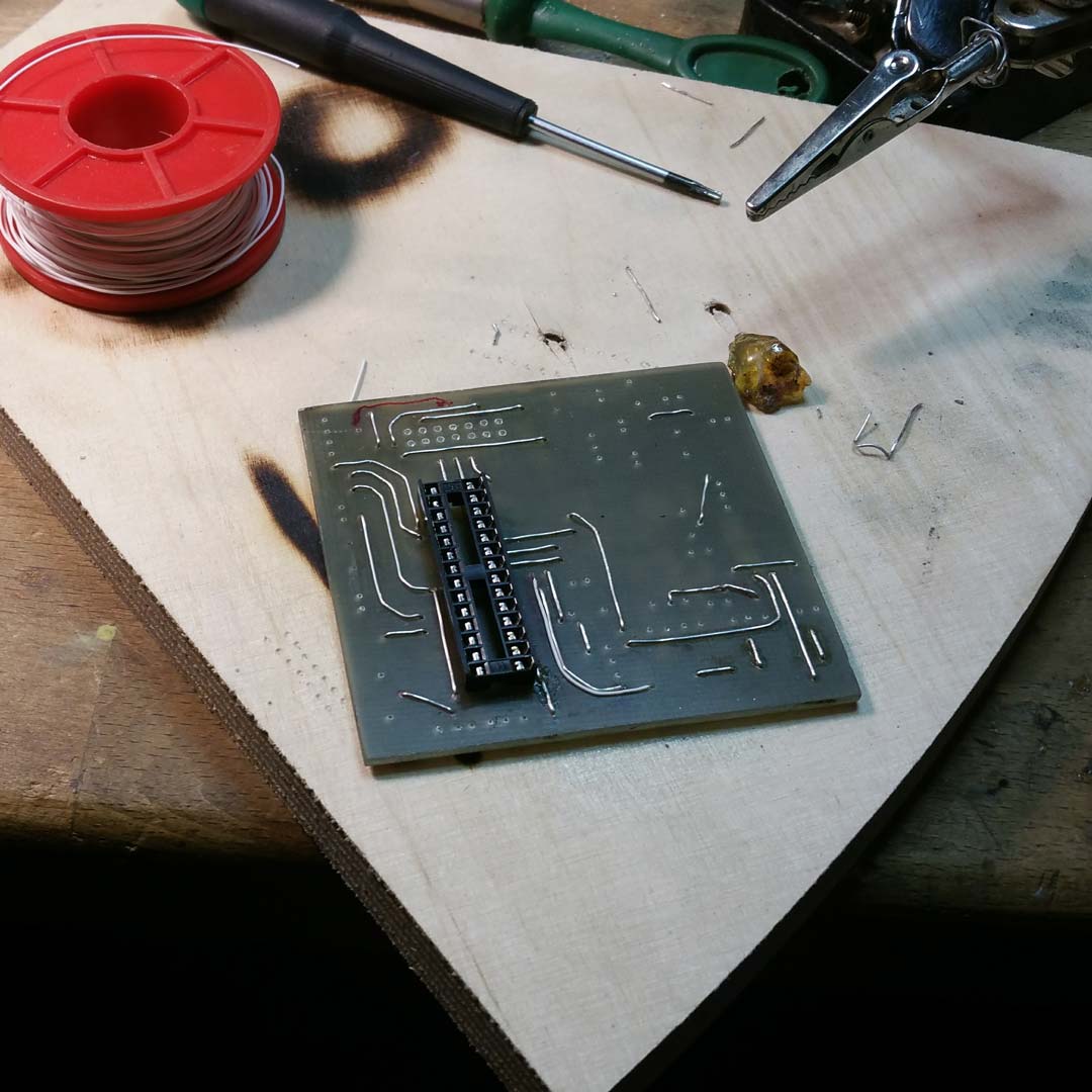
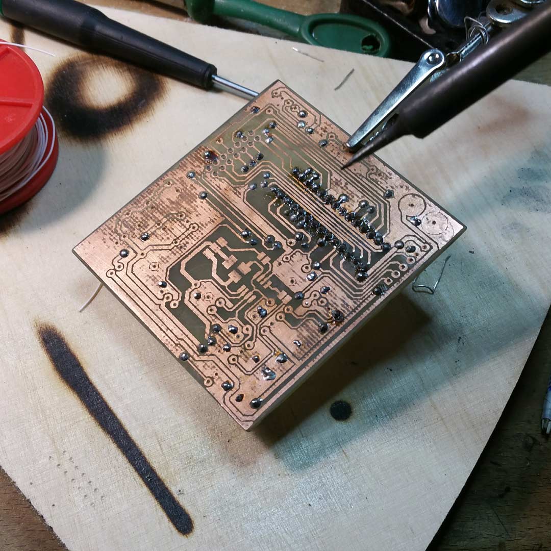
I opted for an in-house manufacturing process for the circuit boards of this project because I was not willing to lose time waiting for factory-produced boards to be shipped. Using Press’n’Peel I transferred the layout to the one-sided FR4 board (Figure 5) and after the etching process (Figure 6), I drilled the corresponding holes and placed wire jumpers on the other side where required, as seen in Figures 7 and 8. At the end of the production and assembly stages, I tested the functionalities of the boards with the embedded C code and also in an electrical way (e.g. monitoring the charging process of the Li-Ion battery with the on-board circuit).


Enclosure Fabrication
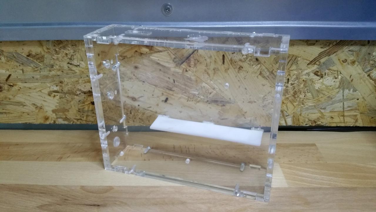
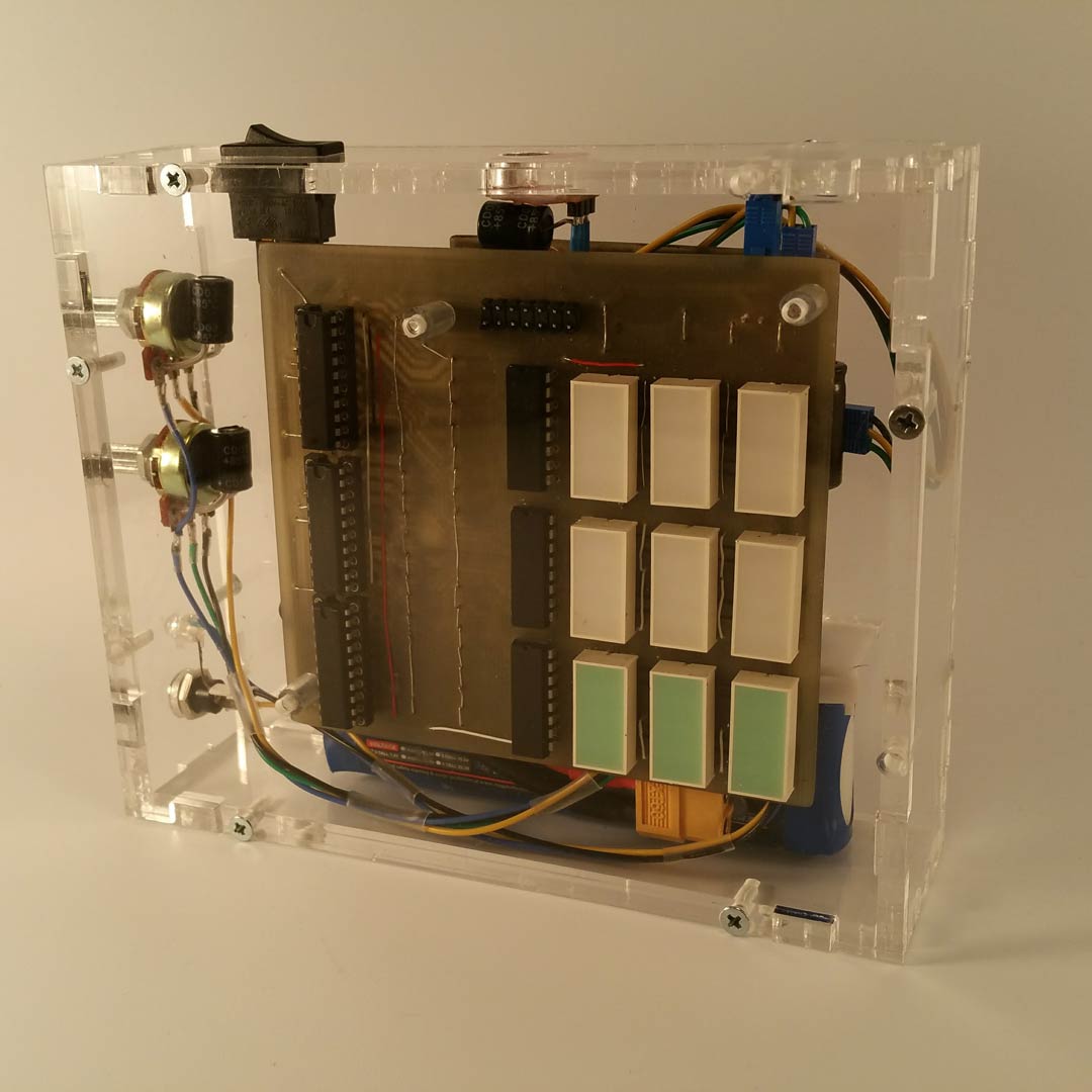
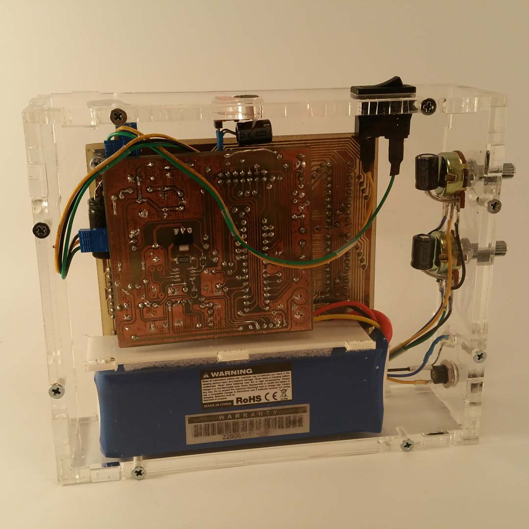
Being already initiated in the laser cutting process which I had experienced at Modulab during the development of projects such as Dexter v1 I developed a nice and neat enclosure solution for Soundwaze made of transparent perspex which you can see in Figure 10. After all, there was nothing to hide inside and the carefully crafted circuit boards could be proudly exposed to any curious viewer!

Final Product
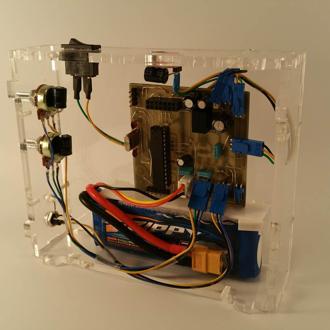
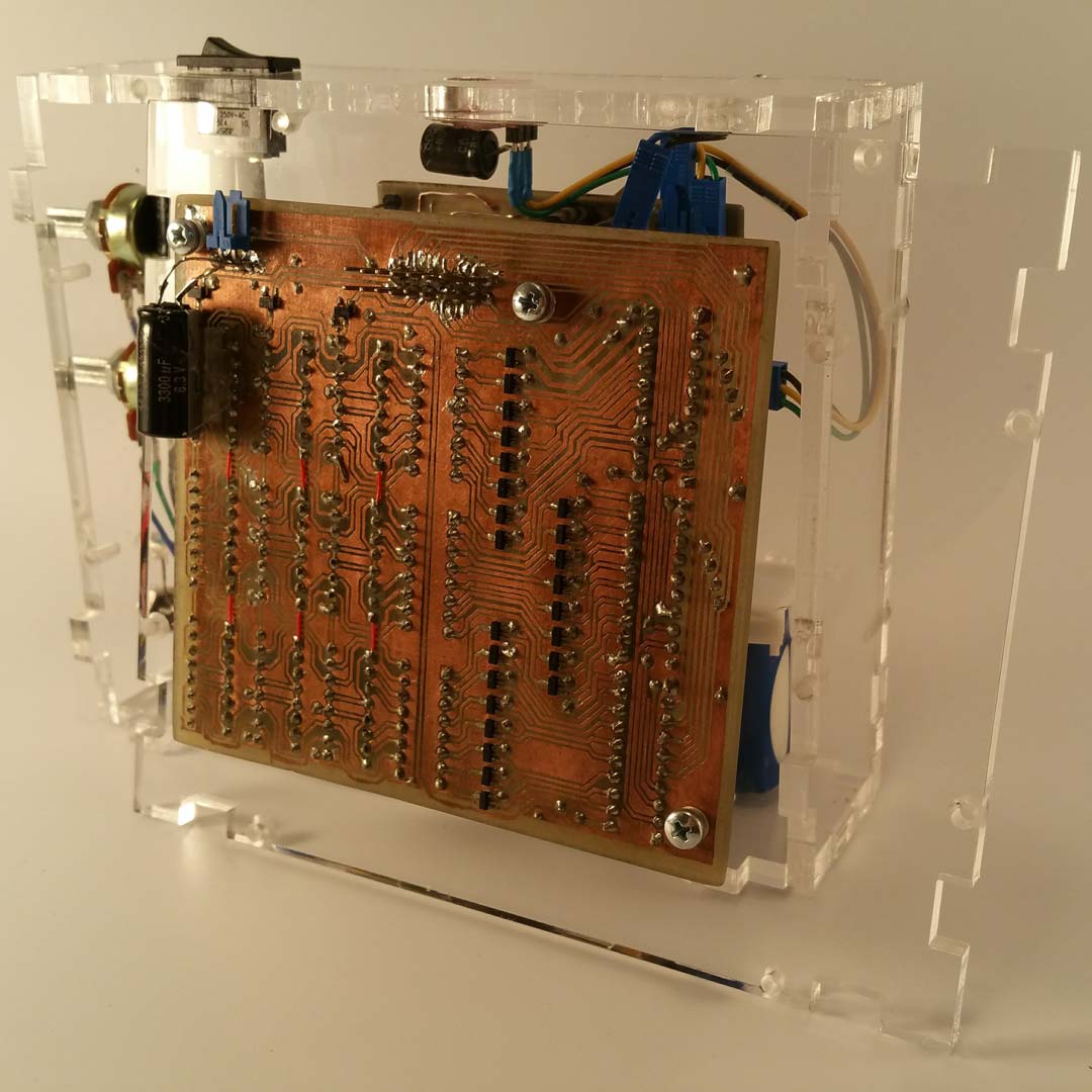
The final product in a crystal-clear transparent perspex enclosure is displayed in Figures 11 to 14. You can also notice the main power switch, the two fine tunning potentiometers, and the Sparkfun microphone breakout. Looking back I can now say that all this project’s functions could be easier performed using a couple of LM3914 circuits (ICs used to display the magnitude of an analog signal). However, all the time allocated to circuit board design and debug combined with the one consumed for software development in this project served as a good learning path for me at that time.


