At the beginning of 2016, I came across an 8×32 dot-matrix display and I decided that an interesting application for this would be a slither game, exactly what Sliter DOT is. The game also included four buttons used to control the snake moves or to increase its speed (high-speed option). It also includes a non-volatile function for storing the high-scores from previous games, without the option to include a name since there is no keyboard input available. Slither DOT also includes a Li-Po battery, a battery level indicator with 10 LEDs, and a charging circuit from a +12V external power supply. You can check this project’s git repository here and also explore the Fusion 360 3D design for Slither DOT right in your browser here.
Hardware Design
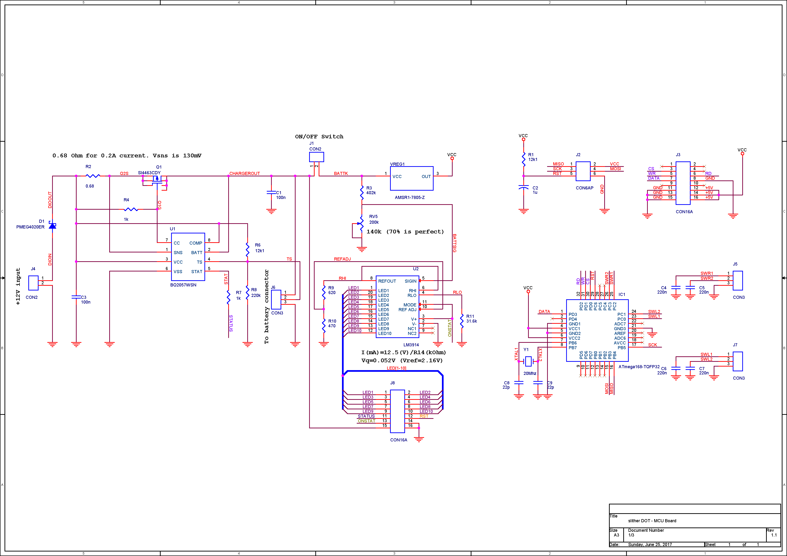
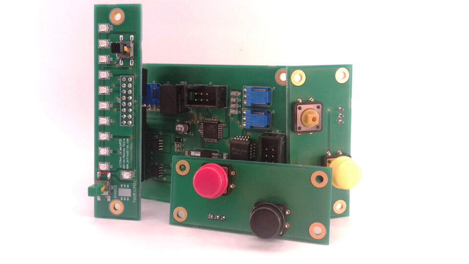
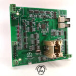
I divided the electronics circuit into 4 boards, 2 with the left and right buttons, 1 with the battery level indicator and a reset button, and the last one with the ATMEGA168 microcontroller, the BQ2057WSN battery charger, the battery level circuit LM3914, and the +5V DC-DC switching regulator AMSR1-7805. The last one’s electric schematic is displayed in Figure 2. The two 16-pins connectors are of IDC type due to their use of mounting and cabling.
Product Design
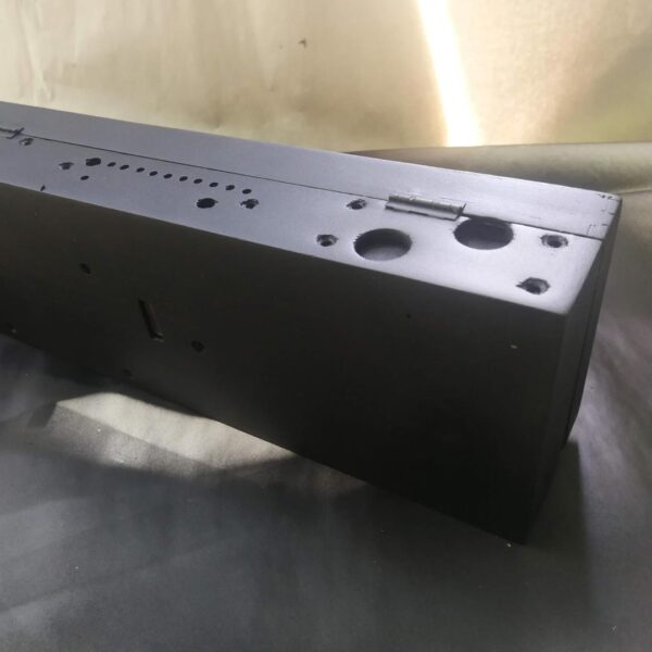
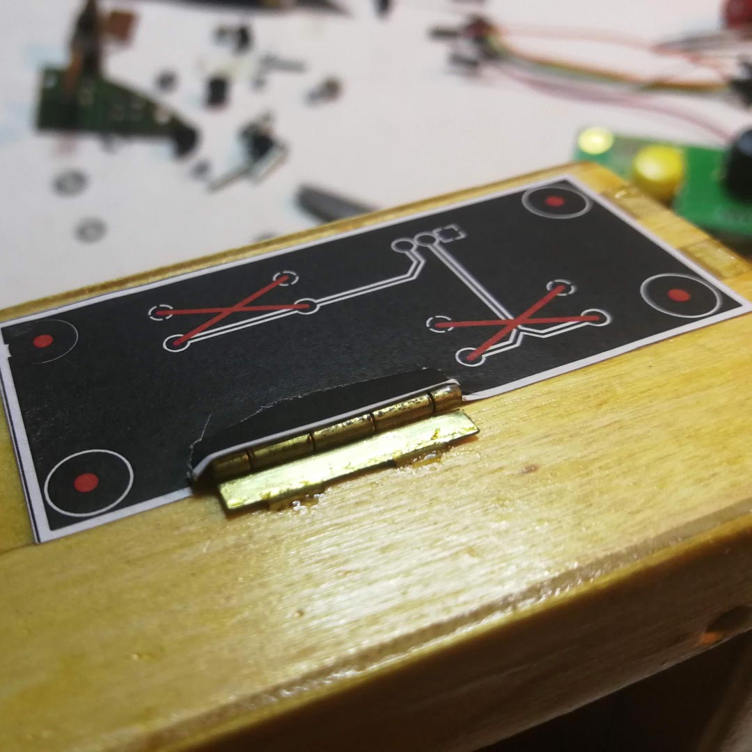
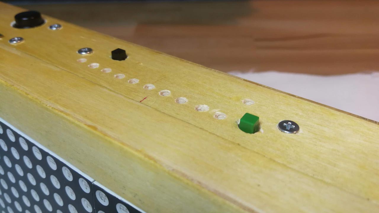
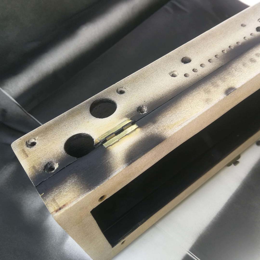
At the current time of development of this project, I didn’t have any knowledge in 3D Design, 3D printing, and Laser Cutting so I had once again to find a prototype way of fabricating an enclosure, as was also the case of Sequenster in the past. I decided to use a wooden box perfectly fitting the 8×32 dot-matrix display in which I carefully drilled holes for all 4 circuit boards usually using a paper template, as you can see in Figures 3 to 7. Finally, I covered the box with two matte black paint layers as displayed in Figure 8 and Figure 9.


PCB Fabrication and Assembly
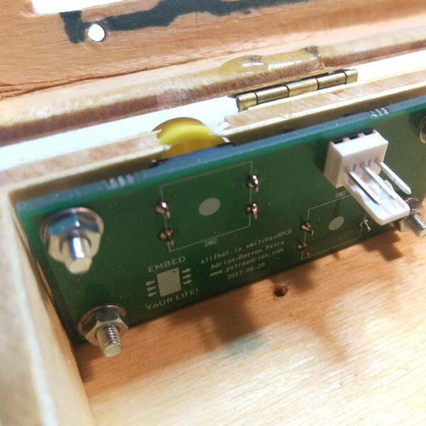
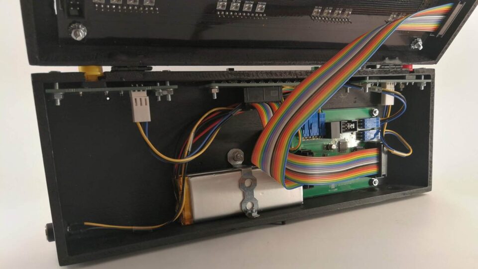
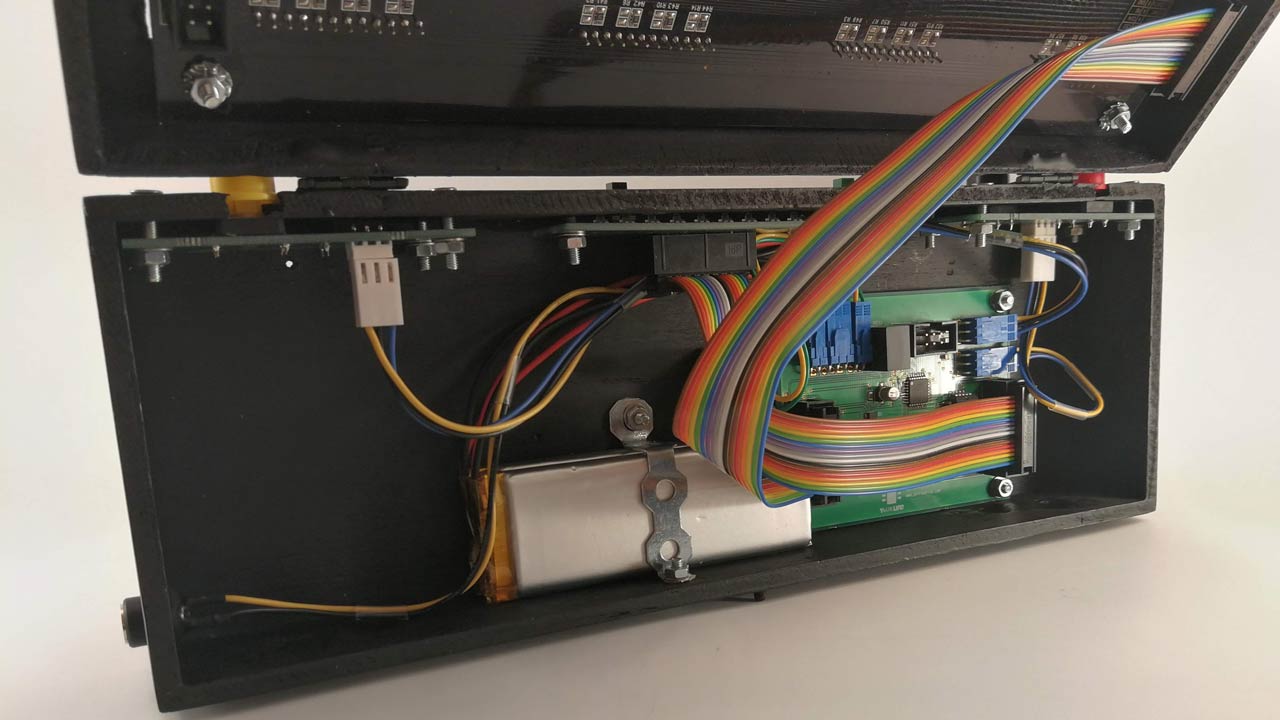
In Figure 10 are displayed the 4 circuit boards completely assembled. You may observe some wire jumpers on the PCB LEDs and also near the microcontroller because I had I few errors in my initial design which I could easily correct in this way. The PCB LEDs also includes a battery charging in progress status LED and a restart button for the MCU. The inside of the enclosure is displayed in Figure 11 where all the circuits are in place finally wired.
Final Product
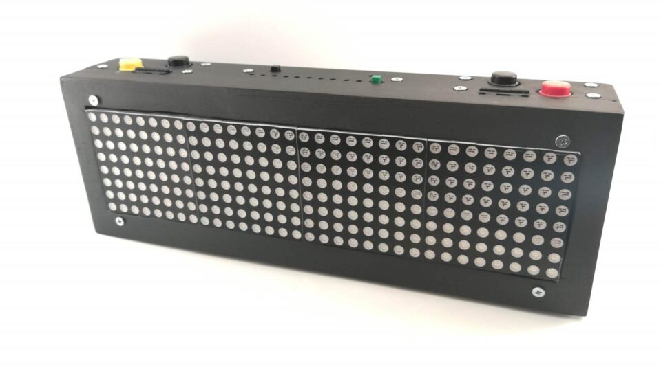
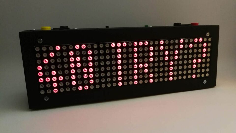
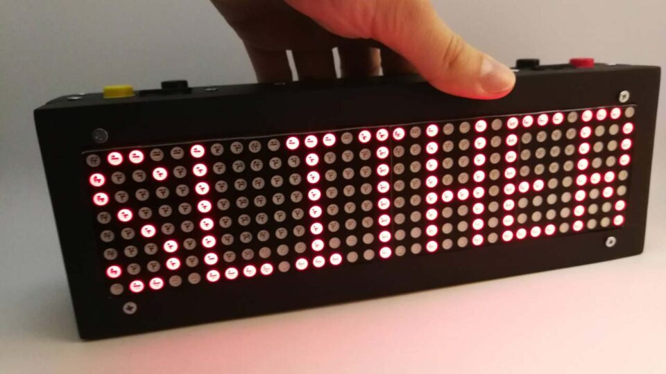
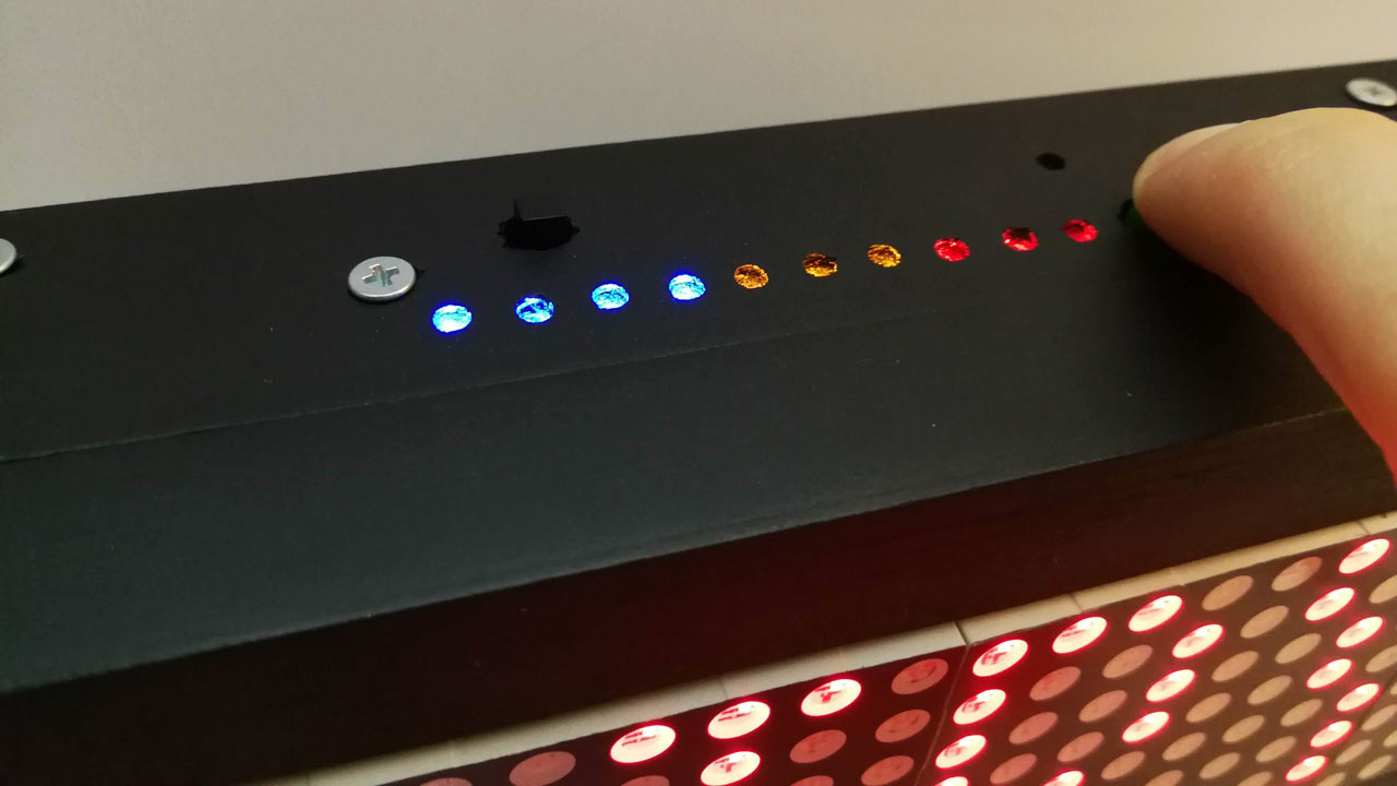
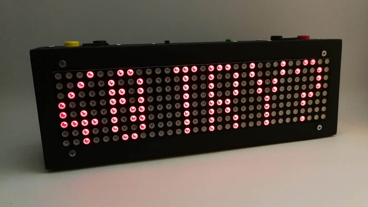
The battery level indicator from Figure 12 should have had the last 4 LEDs of green color completing the low-medium-high scale of colors but I accidentally ordered blue ones and decided to just go with the flow on this last-minute change. You can observe the final product Slither DOT in Figure 13 and Figure 14. I should also mention that in Figure 13 you can see the highest score retained in the EEPROM memory of the MCU in a non-volatile way. This value can however be erased by simultaneously pressing a combination of two buttons. Not displayed in these figures is the main power switch placed on the back of the box.


