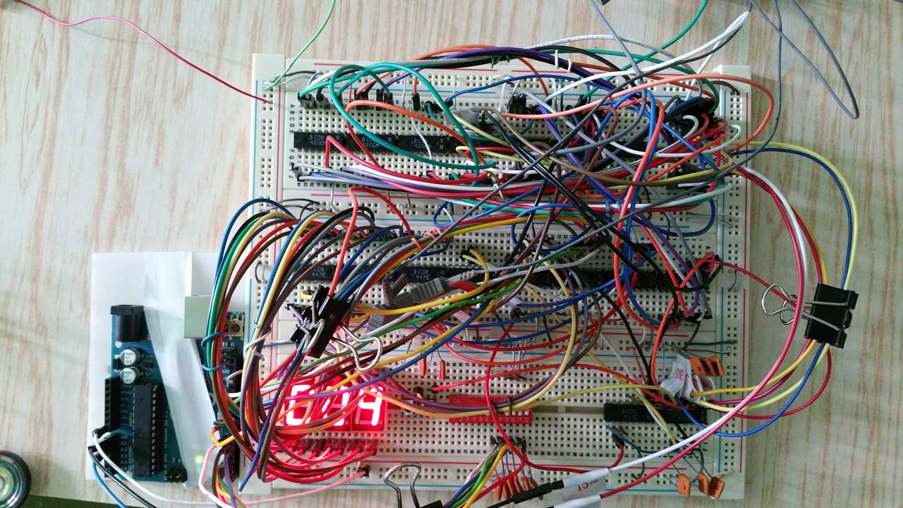
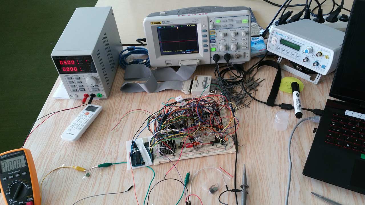
In the summer of 2015 I was looking for a new electronics project to develop, test, and measure with a Rigol DS1102D Oscilloscope I had in my laboratory at the Faculty of Electronics. Because the scope also had a 16-channels digital extension kit and since I was also curious about the digital design I choose to develop a decimal counter with load and reset functions using nothing more than digital circuits such as gates, inverters, decoders, and so on. The project was called Mealy Counter and you can see its prototype in Figure 1.
mealy counter
I designed the circuit as a finite-state machine using the Mealy formalism, where output values are determined both by its current state and the current inputs (in contrast with Moore where they are determined solely by its current state). The machine has three states, IDLE, COUNT, and BLINK’n’RING. In the first one, it awaits the press of the START button, which transitions the machine to the COUNT state, where it counts second by second until it reaches the value loaded in a 12-bits DIP switch. The counting result is also displayed on a seven-segment display. When the counting is completed, the machined enters the BLINK’n’RING state where it blinks the display a couple of times and also rings a small bell. Finally, it returns to the IDLE state. By pressing in any state the RESET button, the user can immediately force return the machine into the IDLE state.

Hardware Design
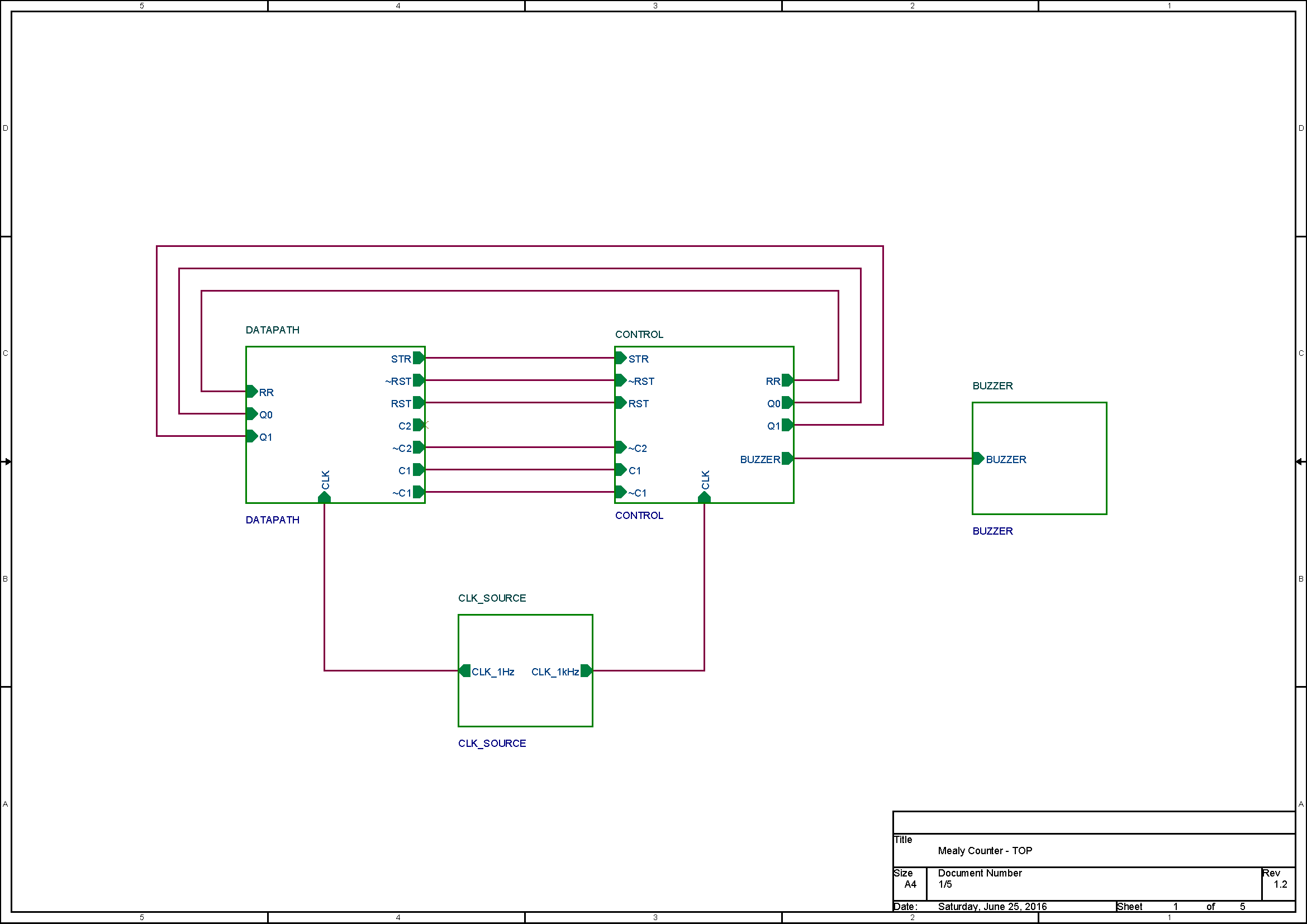
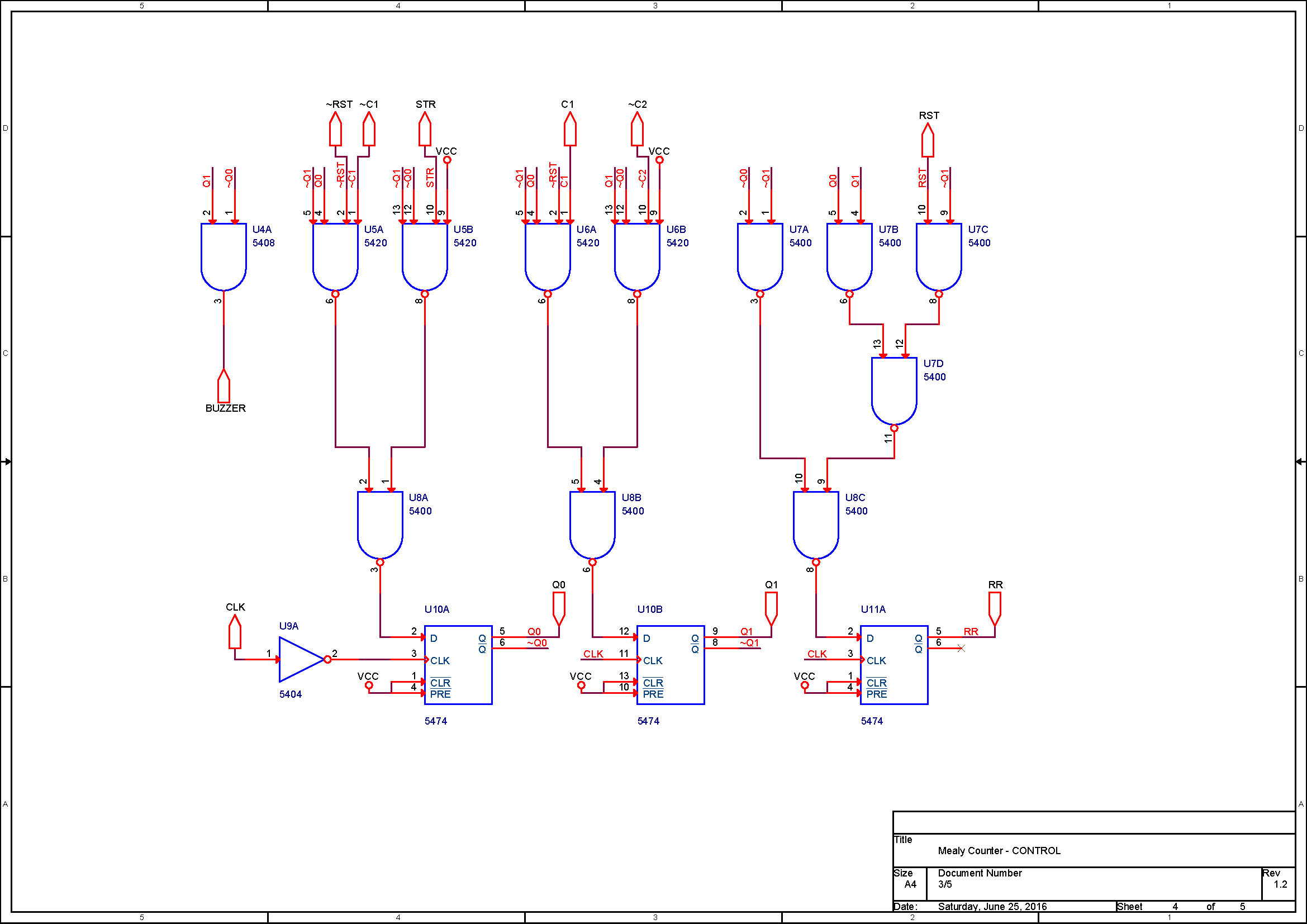
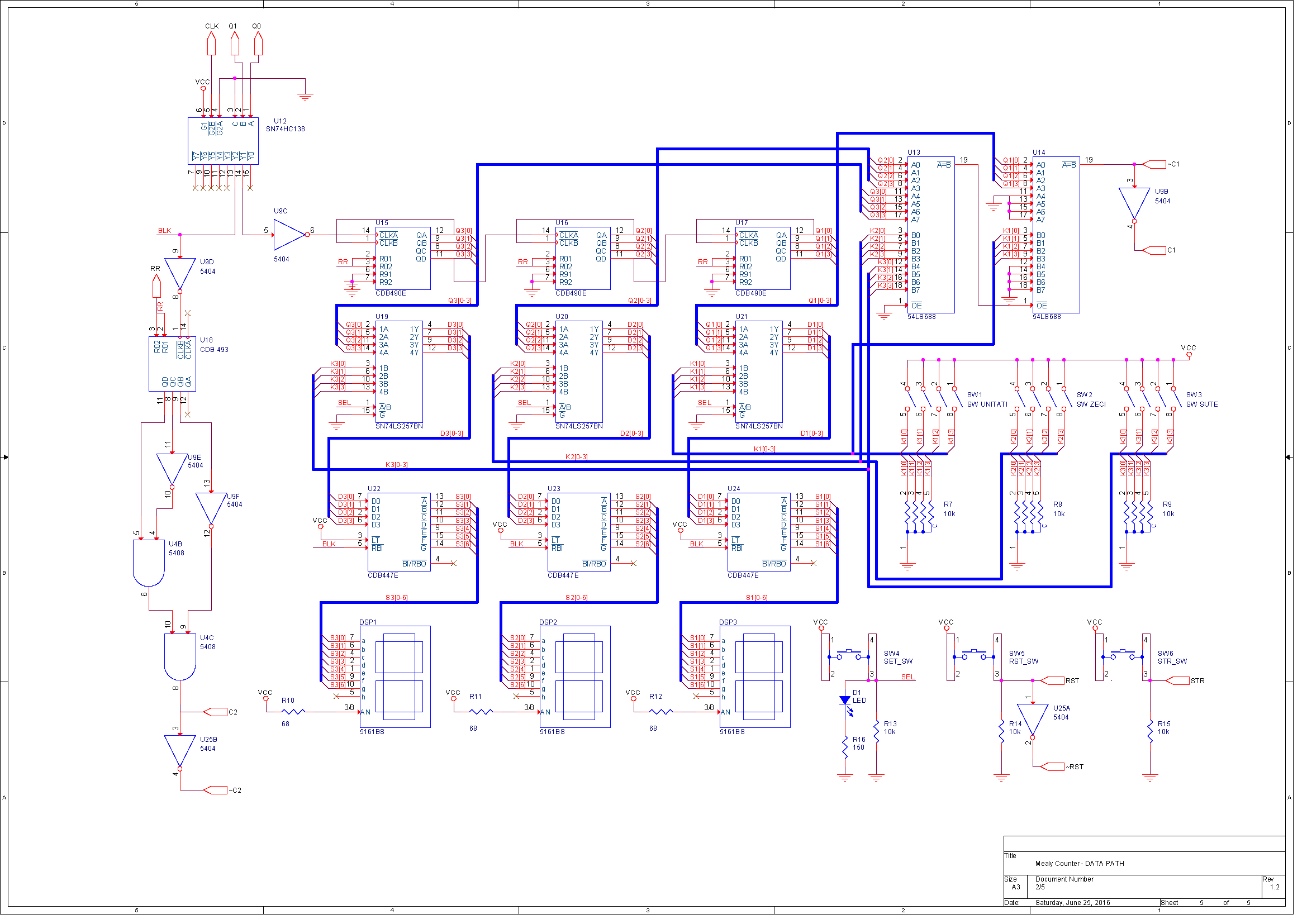
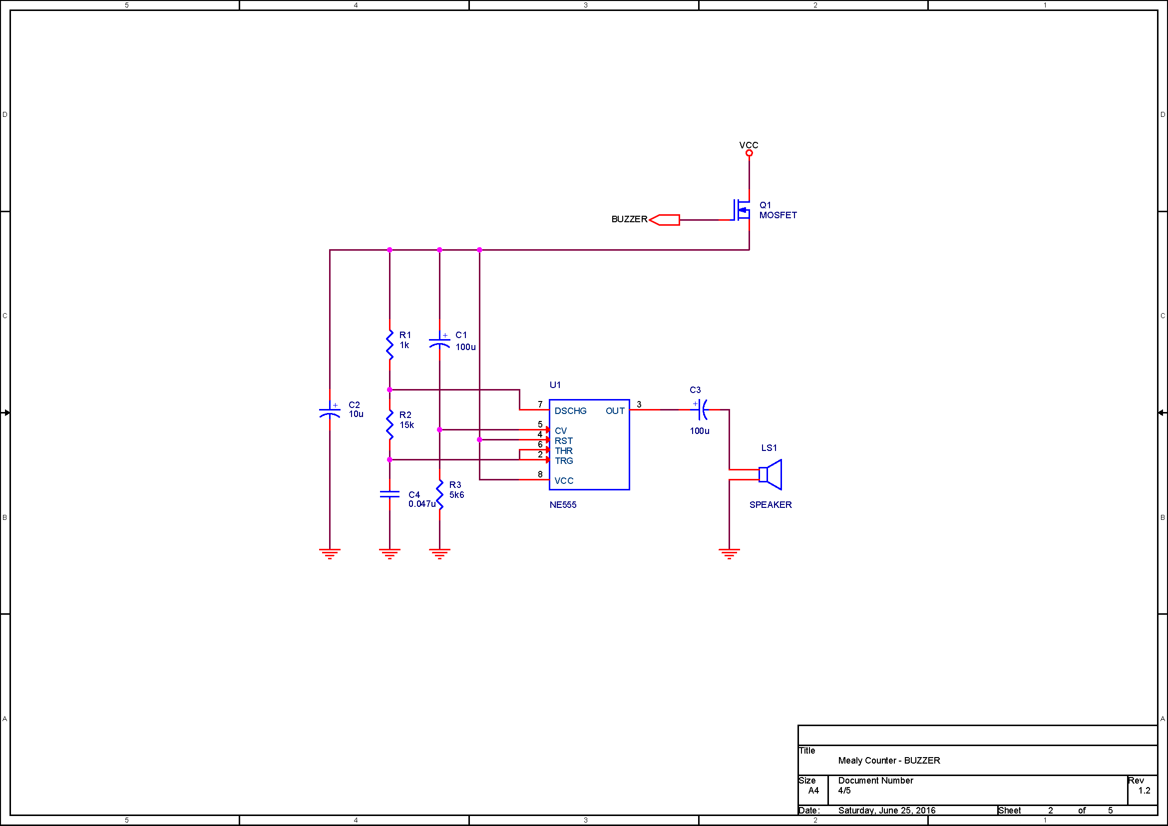
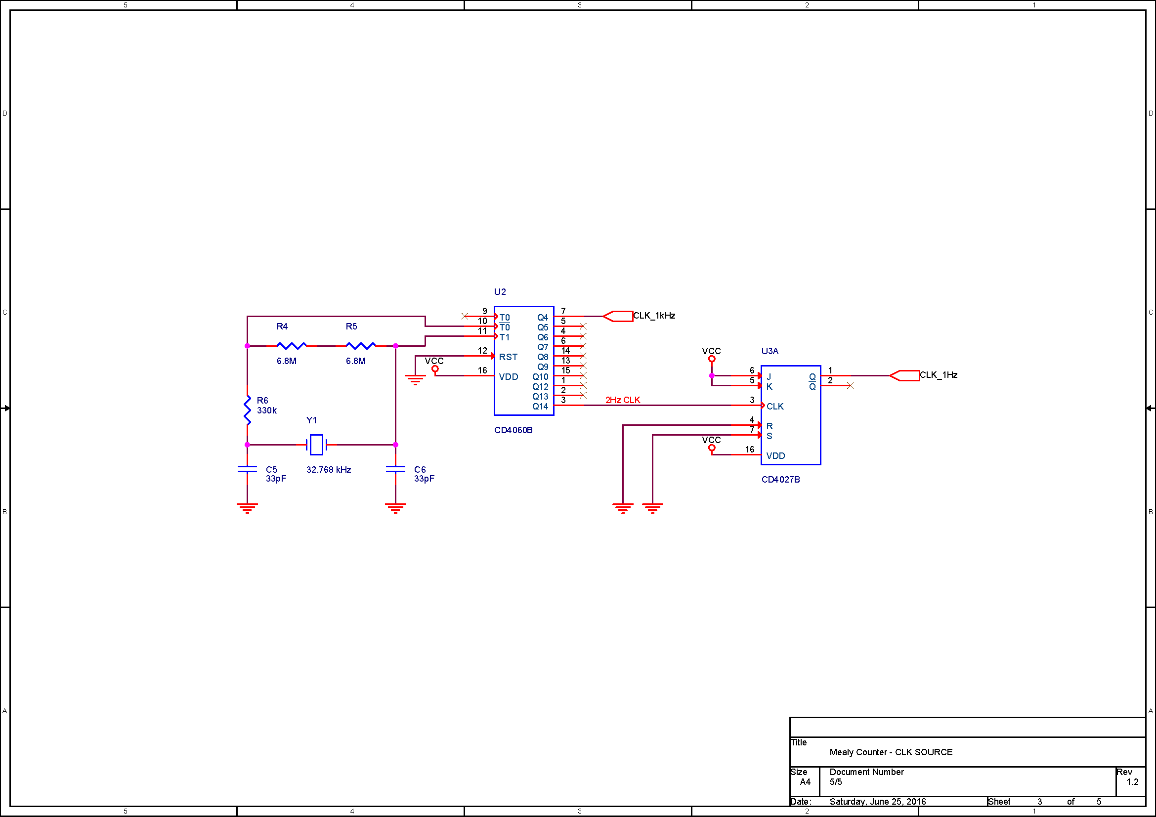
I won’t dive too deep into the details of the design for this machine but I have however attached its electric schematics below in Figures 2 to 6. Displayed in Figure 2 is a block diagram of the system, where you can identify a functional block for data processing and one for commands (Mealy formalism separates these two flows in two different circuits). Also in Figure 2, there are present two more blocks, a Clock Source, and a Buzzer, the first implemented with a 32768Hz crystal and a CD4060 counter used as a frequency divider and the second with a NE555 oscillating as a buzzer. These two functional blocks are not present in the images and video media attached to this post where the clock was provided externally.
Final Product
As you can see in Figure 7, I tested and debugged a lot of the circuit before getting it to work and I must say that this was the most interesting part. Debugging took most of the time for this project since you can imagine how likely the wires were not to make proper contact on that sketchy breadboard structure. Learning more about oscilloscopes, how to set them, and how to measure digital signals with a real hands-on application was the true benefit of this project which I unfortunately never got the chance to finally design on a PCB structure as I intended at that time.


